
Related Manuals for Amprobe BT-120


Summary of Contents for Amprobe BT-120
- Page 1 Circuit Tracer Transmitter BT-120, BT-250 Breaker Tracer User Manual Circuit Tracer Receiver .800.561.8187 information@itm.com www. .com...
- Page 2 BT-120 BT-250 Breaker Tracer User Manual 8/2018, 6011458B ©2018 Amprobe All rights reserved. Printed in China .800.561.8187 information@itm.com www. .com...
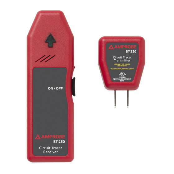
- Page 3 BT-120 BT-250 Breaker Tracer Circuit Tracer Transmitter Circuit Tracer Receiver Sensor Location Identification Arrow LED Indicator Battery Compartment ON/OFF Switch Adaptor Prongs Transmitter Power LED Indicator Receiver Power LED Indicator .800.561.8187 information@itm.com www. .com...
-
Page 4: Table Of Contents
BT-120 BT-250 Breaker Tracer CONTENTS SYMBOLS AND WARNINGS ..................2 Safety Information ...................2 Warnings and Precautions ................3 UNPACKING AND INSPECTION ................3 INTRODUCTION .....................4 OPERATION ......................4 SPECIFICATION ......................5 BATTERY REPLACEMENT ..................7 MAINTENANCE AND REPAIR ................7 .800.561.8187 information@itm.com www. .com... -
Page 5: Safety Information
[Note: Canadian and US.] Safety Information • The BT-120 Breakers Tester is conformed to UL 61010-1; CAT II 120 V, class II and pollution degree 1 or 2. • The BT-250 Breakers Tester is conformed to UL 61010-1; CAT II 250 V, class II and pollution degree 1 or 2. -
Page 6: Unpacking And Inspection
The Amprobe BT Series Breaker Tracers work on powered systems from 90 to 120 V AC (BT-120) and 90 to 250 V AC (BT-250) and are designed for use in residential and light commercial environments. Both kits comes complete with a Transmitter and Receiver. -
Page 7: Operation
OPERATION Breaker and Fuse Identification 1. Plug the Transmitter into an energized wall outlet (Figure 1). Figure 1 2. Make sure the red LED is ON to indicate that the outlet is energized. 3. Push the Power switch on the Receiver to turn it ON. The Receiver will beep and the Power LED will be lit. - Page 8 Using the BT-LFA Incandescent Light Fixture Adapter (BT-250 only) 1. Remove the light bulb exercising the proper caution. 2. Screw in the BT-LFA adapter. 3. Plug the Transmitter into the BT-LFA (Figure 3). Figure 3 4. Preform scan following directions in step 4 under “Operation.” Using the BT-VLA High Voltage Leads Adapter (BT-250 only) The BT-250 Transmitter can be used alone on 110V circuits.
-
Page 9: Specification
SPECIFICATIONS Operating & Detection BT-120 BT-250 90-120 VAC, 90-250 VAC, Voltage for Transmitter Not to exceed ±10% Not to exceed ±10% (inclusive in rating) (inclusive in rating) Operating Frequency 50 Hz to 60 Hz 40 Hz to 70 Hz Storage Temperature 32 °F to 104 °F (0 °C to 40 °C) -
Page 10: Maintenance And Repair
MAINTENANCE AND REPAIR If there appears to be a malfunction during the operation of the tracer, the following steps should be performed in order to isolate the cause of the problem. 1. Check the battery. Replace the battery immediately if the Receiver LED doesn’t turn ON.
Need help?
Do you have a question about the BT-120 and is the answer not in the manual?
Questions and answers