
Related Manuals for LAI Games HYPERshoot


Summary of Contents for LAI Games HYPERshoot
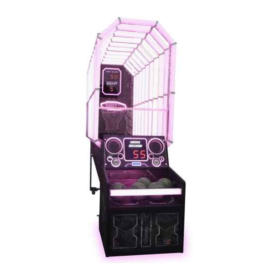
- Page 1 OPERATORS MANUAL Version 10 HYPERshoot Firmware Version 5.00.000 PLEASE NOTE Read this manual before operating the machine. Visit www.laigames.com for support.
- Page 2 Authorization is hereby provided to you to copy this manual in its entirety provided such copies are used for non-commercial purposes and solely for use with LAI Games products. This authorization is specifically conditioned to include all legends, copyright, proprietary and other notices which appear herein are...
-
Page 3: Table Of Contents
Table of Contents SAFETY PRECAUTIONS ..........................6 MACHINE INSTALLATION AND INSPECTION ................... 7 INTRODUCTION ............................8 DESCRIPTION ............................8 PACKAGING ............................. 8 CONTENTS ............................8 SPECIFICATIONS ..........................8 DIMENSIONS ........................... 8 ELECTRIC SUPPLY..........................8 PACKAGING DETAILED ........................10 ASSEMBLY ............................. 10 PARTS DETAILED.......................... - Page 4 BASKET SENSOR ..........................32 BACKBOARD DISPLAY ........................33 SHOWING INVALID INFORMATION ....................33 SECTION A: SERVICE INSTRUCTIONS ..................... 34 LOCATING AND ACCESSING PARTS ....................... 34 CABINET FRONT ..........................34 BACKBOARD ..........................35 PLAYER PANEL ..........................35 CABINET INNER ..........................36 OPERATOR PANEL / SERVICE CONTROLS ..................
- Page 5 FB216 UPDATE PROCEDURE ......................... 42 TOOLS REQUIRED ..........................42 PC SETUP ............................42 FLASHER-STM32 ..........................42 PROCEDURE ............................43 TROUBLESHOOTING .......................... 47 SECTION B: TECHNICAL DETAILS ......................49 POWER SUPPLY ..........................49 COIN OPTIONS REFERENCE GUIDE ....................50 UNIVERSAL CARD LINK CONNECTION ....................50 TICKET MECHANISMS ........................
-
Page 6: Safety Precautions
SAFETY PRECAUTIONS The following safety precautions and advisories used throughout this manual are defined as follows. WARNING: Disregarding this text could result in serious injury. CAUTION: Disregarding this text could result in damage to the machine. NOTE: An advisory text to hint or help understand. PLEASE READ THE FOLLOWING WARNING: Always turn OFF Mains AC power and unplug the game before opening or... -
Page 7: Machine Installation And Inspection
MACHINE INSTALLATION AND INSPECTION When installing and inspecting HYPERshoot, be very careful of the following points and pay attention to ensure that the players can enjoy the game safely. • Be sure to turn the power OFF before working on the machine. -
Page 8: Introduction
INTRODUCTION Congratulations on your purchase of HYPERshoot by LAI Games. We hope you take the time to read this manual and learn about the many features and user-friendly adjustments that can be made to fine-tune the game for maximum earning potential. - Page 9 LOCATION REQUIREMENTS • Ambient temperature: 5C - 40C • Ambient humidity: • Ambient U.V. radiation: Very low • Vibrations level:...
-
Page 10: Packaging Detailed
PACKAGING DETAILED ASSEMBLY PARTS DETAILED... -
Page 11: Assembly Steps
ASSEMBLY STEPS 1. Remove 8 x M10 hex bolts on the backboard and unmount it. 2. Remove 2 x M10 hex bolts from the support brackets on either side of the cabinet (4 x M10 bolts total) and put them aside for use in step 4. 3. - Page 12 4. Lock the rear chaser light section in place using the 4 x M10 hex bolts (2 x bolts per side) from step 1. 5. Replace the backboard, and secure it using the same 8 M10 hex bolts that were removed in step 1.
- Page 13 7. Lock the front chaser lights section in place using 2x M10 hex bolt per side (4 x bolts total.) 8. Slide the front cabinet out from underneath the main cabinet and unpack it. 9. Unlock the caster wheels on the main cabinet and remove it from the pallet.
- Page 14 10. Plug in all 10 connectors along the left side for the chase lights, and 2 connectors at the front for the sensors. CAUTION: DO NOT step on the ball gate. This can result in damage to the mechanism. 11. Locate the hoop component and insert the connector through the access hole. 12.
- Page 15 13. Install the cable tie holder and hoop harness as shown below. 14. Plug the connectors at the left and right sides in. 15. Locate and remove the 6 screws shown below. 16. Install the connector brackets at locations 1, 2 and 3. Location 1 and 3 use the same bracket. 17.
- Page 16 If you have a marquee to install, please continue to step 19 below. If you are not installing a marquee, please skip ahead to step 26. 19. Position the two cabinets next to each other and place the bracket in between, aligning the screw to the bracket keyholes.
- Page 17 24. Position the marquee at the top, between the two units. 25. Locate the mounting brackets shown, and lock the marquee in place using 4 x M5 locknuts. 26. Remove 6 x M10 screws from the rear of front cabinet. 27.
- Page 18 29. Power up the game and ensure that all lights and sensors are functioning correctly. 30. Install 2 x side inner covers (packed separately). 31. Install 2 x bottom connector covers (packaged separately) using 4 x M4 screws.
- Page 19 32. Remove the 4 x M5 hex bolts shown. 33. Install the acrylic shield in place at the front of the cabinet using the bolts removed in the previous step.
-
Page 20: Gameplay And Modes
Attract mode provides a visual and audio display while the game is not being played. PLAY MODE HYPERshoot has two play modes. The standard Coin Play mode, where a coin or coins are inserted, or Free Play mode, where no coins are necessary. -
Page 21: Operation
OPERATION P SETTINGS Coin 1 Coins per Credit Default 1, Adjustable 1 – 20 Sets the number of coins that need to be inserted in exchange for each game credit. Coin 1 Games per Credit Default 1, Adjustable 1 – 20 Sets the number of games granted for each credit. - Page 22 Coin 2 Multi Bonus Credits Default Off, Adjustable On / Off Turn on the first stage of bonus credits for coin mech 2. Turning this setting on, will activate settings 6-1 to 6-6. Coin 2, Stage 1, Number of Coins 6.1.
- Page 23 Prize Type Default Ticket, Adjustable Off / Ticket / Coupon Defines the type of prize given to the player. This only affects how the jackpot number and tickets owing number is displayed. If set to "Off" then no prize is paid out and P15 is hidden. If set to "Tickets"...
- Page 24 Bonus Ticket / Bonus Credit Default Tickets - 50, Credits – 1, Adjustable Tickets 1-5000, Credits 1 Sets the quantity of bonus items awarded, depending on the value of the “Bonus Type” setting. If “Bonus Type” is set to None, this setting is hidden. If “Bonus Tickets”...
-
Page 25: Audits
AUDITS 1. Total Coins 1 Shows the number of coins inserted on COIN1 input. 2. Total Coins 2 Shows the number of coins inserted on COIN2 input. 3. Total Service Credits Shows the number of times the service button was used to issue 1 credit to the game. 4. -
Page 26: Input And Output Tests
21. Av Number of 2pt Baskets Average number of 2 point baskets per game 22. Av Number of 3pt Baskets Average number of 3 point baskets per game 23. Av Number of 4pt Baskets Average number of 4 point baskets per game 24. -
Page 27: Input Tests
INPUT TESTS The display will read ON or OFF to indicate if the currently selected input is active or not. • Up Button • Down Button • Test / Enter Button • Service / Back Button • Utility Button • Single Player Button •... -
Page 28: Errors
ERRORS Name Cause Solution Refill the ticket mechs and ensure there is no jam. Clear the error by The game has run out of tickets viewing it in the errors menu and Error ticket or if there is a jam on ticket pressing the right button. -
Page 29: Hard Errors
Check the ball gate sensors are operating correctly and are not Ball gate sensors are not jammed. Ball Gate Error reading expected values. Use the run tests menu to ensure that the ball gate motor is running correctly. The CPU cannot read or write Clear the error by viewing it in the Error EEP NJ to its on-board EEPROM New... - Page 30 Check that the sensor is not dirty or blocked by anything. Use the operator menu input tests to check that the Rear Sensor input is triggered when throwing a ball. The rear sensor has been Error Rear Sensor Check that the sensor is connected reported as active for too long correctly.
-
Page 31: Troubleshooting
TROUBLESHOOTING SENSOR CALIBRATION The front throw and basket sensors are calibrated by the manufacturer but can be recalibrated if the game isn’t functioning as expected. Using differently colored or dirty basketballs may effect the calibration. FRONT THROW SENSOR The front throw sensor detects when a ball is thrown. One receiver PCB contains 8 receive sensors connected to 1 adjustment trimpot. -
Page 32: Basket Sensor
BASKET SENSOR The basket sensor calibration ensures it properly detects any balls that pass through the basket. Incorrect calibration will result in the ball not being detected when passing through the basket or the ball being incorrectly detected when outside the basket. The sensor can be adjusted to increase and decrease the sensitivity, until the balls are detected correctly. -
Page 33: Backboard Display
BACKBOARD DISPLAY SHOWING INVALID INFORMATION If the backboard display is showing unclear or invalid information, it’s possible that p setting 23, Shot Clock Position, has been set incorrectly. 1. Establish if your shot clock value is displayed on the backboard or on a front panel. 2. -
Page 34: Section A: Service Instructions
SECTION A: SERVICE INSTRUCTIONS NOTE: Be sure to read the following carefully before servicing the machine LOCATING AND ACCESSING PARTS The following pictures identify the location of the main serviceable items. CABINET FRONT 1. Backboard 2. Chase lighting 3. Player panel 4. -
Page 35: Backboard
BACKBOARD 1. Shot clock display 2. Points per basket display 3. Basket sensors PLAYER PANEL 1. Score display 2. Link player count display 3. Link player button 4. Credit display 5. Singly player button 6. Speakers 7. High score lamp... -
Page 36: Cabinet Inner
CABINET INNER 1. Amplifier 2. Power inlet 3. Subwoofer 4. Power supply 5. Operator panel 6. FB216 Game IO PCB 7. FB215 PWM Driver PCB 8. FB106 Sound PCB... -
Page 37: Operator Panel / Service Controls
OPERATOR PANEL / SERVICE CONTROLS 1. Up button 2. Back / service button 3. Down button 4. Volume control 5. Coin 1 counter 6. Count 2 counter 7. Test / enter button 8. Ticket counter 9. UCL connector 10. Utility button BALL GATE 1. -
Page 38: Link Connectors
LINK CONNECTORS Up to 8 HYPERshoot games can be linked together for competitive play. Daisy-chain the games together by connecting the supplied Link Cable to the IN and OUT connectors on each machine. Games on the end positions of the link only need a single cable connection. -
Page 39: Ball Gate
FB63 7-Segment Display PCBs are used to display the game time remaining, and the current points per basket. Access is from the rear of the game. LED LIGHTING/FB215 16 independent LED lighting channels are used in HYPERshoot. Each channel is fused and driven by the FB215 PCB. Channels 1-10 are used on the chase lights... -
Page 40: Operator Panel Volume Knob
OPERATOR PANEL VOLUME KNOB Use to adjust the speaker’s sound level. GAME BOARD – FB216 The FB216 is the main control board for the game. It contains the application firmware and output drivers to read sensor inputs and control the lighting, displays and audio. It has five fuses, the ratings of which can be seen in the image below: COIN MECHANISM / BILL ACCEPTOR / CARD SYSTEM Credits can be inserted via a coin mech, bill acceptor and/or card system connection. -
Page 41: Lamps
Always replace the lamps with the same or equivalent size, wattage and voltage. All button lamps are 12VDC T10 LED or equivalent. All remaining lighting is RGB LED strip. Contact your nearest LAI Games office for replacement LED strip to ensure color is matched. MAINTENANCE EXTERIOR •... -
Page 42: Fb216 Update Procedure
FB216 UPDATE PROCEDURE TOOLS REQUIRED • 1 x USB – TTL Serial Adapter with Connector Harness • 1 x PC or Laptop with USB Port running a Windows OS (will be connected to game during the update, so must be portable) •... -
Page 43: Procedure
PROCEDURE 1. Switch off the game that is being updated 2. Access the required service area and locate the PCB (refer to Locating and Accessing parts – Cabinet Inner for assistance in locating FB216) 3. Place the PC near the PCB, and connect them using the USB – TTL serial adapter cable, from the USB port on the PCB, to the J5 programming port on the PCB 4. - Page 44 6. For the Port Name setting, open the drop-down menu and select the only COM port available (COM number is automatic and can vary). If you’re unable to proceed to the next step when pressing next, restart the PC and try again. 7.
- Page 45 9. Press Next 10. Ensure that the target field correctly reads “STM32F4_05_07_15_17_1024K” 11. Press Next 12. Select “Download to device” on the left 13. Click the “…” button on the right hand side of the window, and navigate to and select the HEX file 14.
- Page 46 16. Press Next 17. Above the progress bar, the text will progress from “Downloading,” to “Verifying,” to “Success” 18. Once the progress bar is green and states “Download operation completed successfully,” press Close to finish 19. Turn off the game 20.
-
Page 47: Troubleshooting
TROUBLESHOOTING NO COM PORT SELECTABLE FROM DROP DOWN If you’re up to step 6, and there are no options to select a port from the drop-down menu, the PC is not able to communicate with the PCB 1. Ensure the game is powered on, and the PCB has power – verify that the heartbeat LED (shown below) is flashing to ensure that the PCB has power 2. -
Page 49: Section B: Technical Details
SECTION B: TECHNICAL DETAILS WARNING: Always turn OFF mains power and unplug the game before cleaning the interior of the machine. Always after cleaning the cabinet interior, check all harness connectors and restore all loose or WARNING: It is advised that anybody using SECTION B for repairing or modifying any of the interrupted connections. -
Page 50: Coin Options Reference Guide
PIN7 = GND PIN8 = COIN2 input PIN9 = 12VDC Contact your nearest LAI Games distributor for harnessing to suit different coin comparators and bill acceptors. UNIVERSAL CARD LINK CONNECTION A 9 pin Universal Card Link connector exists on the operator panel inside the coin door. -
Page 51: Ticket Mechanisms
Pin 6. Ticket Meter- is connected to the Ticket 1 Meter output from the game PCB and can be used by card systems for monitoring purposes. Pin 7. Empty Pin 8. Empty Pin 9. Ground- is connected to the common Ground connection, the same ground as the Game PCB. TICKET MECHANISMS A ticket mech can be fitted inside the ticket doors. - Page 52 7 WAY JST - USER BUTTON CPU PIN FUNCTION NAME DESCRIPTION 12VDC Button lamp power Logic ground for button switches (switch COMMON) PE10 BTN1_SW Button 1 switch (switch NO) PE12 BTN2_SW Button 2 switch (switch NO) BTN1_LAMP Low-side driver for button 1 lamp BTN2_LAMP Low-side driver for button 2 lamp Unused ground...
-
Page 53: Wiring Diagrams
WIRING DIAGRAMS (Next Page) -
Page 72: Mechanical Illustrations
MECHANICAL ILLUSTRATIONS MAIN CABINET... -
Page 73: Front Enclosure
FRONT ENCLOSURE... -
Page 74: Rear Enclosure 1
REAR ENCLOSURE 1... -
Page 75: Rear Enclosure 2 And 3
REAR ENCLOSURE 2 AND 3... -
Page 76: Chaser Module Front And Rear
CHASER MODULE FRONT AND REAR... -
Page 77: Front Access Panel And Coin Door
FRONT ACCESS PANEL AND COIN DOOR... -
Page 78: Cash Box Housing And Operator Panel
CASH BOX HOUSING AND OPERATOR PANEL... -
Page 79: Ticket Door, Front Led Cover And Display Front
TICKET DOOR, FRONT LED COVER AND DISPLAY FRONT... -
Page 80: Display Board And Display Panel
DISPLAY BOARD AND DISPLAY PANEL... -
Page 81: Amplifier Bracket, Front Enclosure Panel And Subwoofer Box
AMPLIFIER BRACKET, FRONT ENCLOSURE PANEL AND SUBWOOFER BOX... -
Page 82: Right And Left Side Panel Frame
RIGHT AND LEFT SIDE PANEL FRAME... -
Page 83: Main Pcb Board And Db Box
MAIN PCB BOARD AND DB BOX... -
Page 84: Front And Rear Chaser Lights
FRONT AND REAR CHASER LIGHTS... -
Page 85: Mid 1 And 2 Chaser Lights
MID 1 AND 2 CHASER LIGHTS... -
Page 86: Backboard, Hoop And Backboard Housing
BACKBOARD, HOOP AND BACKBOARD HOUSING... -
Page 87: Basketball Gate And Power Supply
BASKETBALL GATE AND POWER SUPPLY... -
Page 88: Leg Support, Led Base Bracket 1 And 2
LEG SUPPORT, LED BASE BRACKET 1 AND 2... -
Page 89: Ticket Holder, Side Sensor Bracket Right And Left
TICKET HOLDER, SIDE SENSOR BRACKET RIGHT AND LEFT... -
Page 90: Marquee Base And Display
MARQUEE BASE AND DISPLAY... -
Page 91: Full Marquee Assembly
FULL MARQUEE ASSEMBLY... - Page 92 LAI Games shall have no liability related to such improper and unauthorized use and/or operation of the hardware and licensed software, and Operator shall indemnify, defend, and hold LAI Games harmless for any claim or cause of action brought against LAI Games arising from Operator’s or Operator’s representative’s improper and unauthorized use and/or operation of the hardware and licensed software.
- Page 93 LAI Games warrants its manufactured products for a period of 3 months inclusive of parts and labor from the date of sale. LAI Games exclusive obligation is to repair any item with any defects as a result of faulty workmanship or materials, providing the defective item or items of equipment are returned to the LAI Games distributor from which the machine was purchased.
- Page 94 Contact Us sales@laigames.com Sales and Enquiries: support@laigames.com Technical Support: www.laigames.com Website: For your nearest LAI Games Distributor, visit our web site at www.laigames.com...
Need help?
Do you have a question about the HYPERshoot and is the answer not in the manual?
Questions and answers