
Related Manuals for LAI Games Let’s Bounce


Summary of Contents for LAI Games Let’s Bounce
- Page 1 OPERATORS MANUAL Version 15 LET’S BOUNCE Firmware version 9.01.000 PLEASE NOTE Read this manual before operating the machine. Visit www.laigames.com for support.
- Page 2 Authorization is hereby provided to you to copy this manual in its entirety provided such copies are used for non-commercial purposes and solely for use with LAI Games products. This authorization is specifically conditioned to include all legends, copyright, proprietary and other notices which appear herein are...
-
Page 3: Table Of Contents
Table of Contents SAFETY PRECAUTIONS ..........................6 MACHINE INSTALLATION AND INSPECTION ................... 7 INTRODUCTION ............................8 DESCRIPTION ............................8 PACKAGING ............................. 8 CONTENTS ............................8 SPECIFICATIONS ..........................8 DIMENSIONS ........................... 8 ELECTRIC SUPPLY..........................8 PACKING DETAILED ........................10 ASSEMBLY ............................. 11 PARTS DETAILED.......................... - Page 4 BACKBOARD ..........................32 PLAYER PANEL ..........................33 CABINET INNER ..........................33 CABINET REAR ..........................34 CABINET SIDE ..........................35 OPERATOR PANEL / SERVICE CONTROLS ..................35 ACCESSING THE PLAYFIELD ....................... 36 PARTS DESCRIPTION ......................... 38 HEADER DISPLAY ........................... 38 BACKBOARD ..........................38 SPEAKERS ............................
- Page 5 POWER SUPPLY ..........................49 COIN OPTIONS REFERENCE GUIDE ....................50 UNIVERSAL CARD LINK CONNECTION ....................50 TICKET MECHANISMS ........................51 WIRING DIAGRAMS ..........................51 MECHANICAL ILLUSTRATIONS ......................71 MAIN ASSEMBLY ..........................71 FRONT PANEL ............................ 72 PANEL DOOR AND BASE FRONT PANEL .................... 73 COIN DOOR AND TICKET DOOR ......................
-
Page 6: Safety Precautions
SAFETY PRECAUTIONS The following safety precautions and advisories used throughout this manual are defined as follows. WARNING: Disregarding this text could result in serious injury. CAUTION: Disregarding this text could result in damage to the machine. NOTE: An advisory text to help understand. PLEASE READ THE FOLLOWING WARNING: Always turn OFF Mains AC power and unplug the game before opening or... -
Page 7: Machine Installation And Inspection
MACHINE INSTALLATION AND INSPECTION When installing and inspecting Let’s Bounce, be very careful of the following points and pay attention to ensure that the players can enjoy the game safely. • Be sure to turn the power OFF before working on the machine. WARNING: Always turn OFF mains power before removing safety covers and refit all safety covers when work is completed. -
Page 8: Introduction
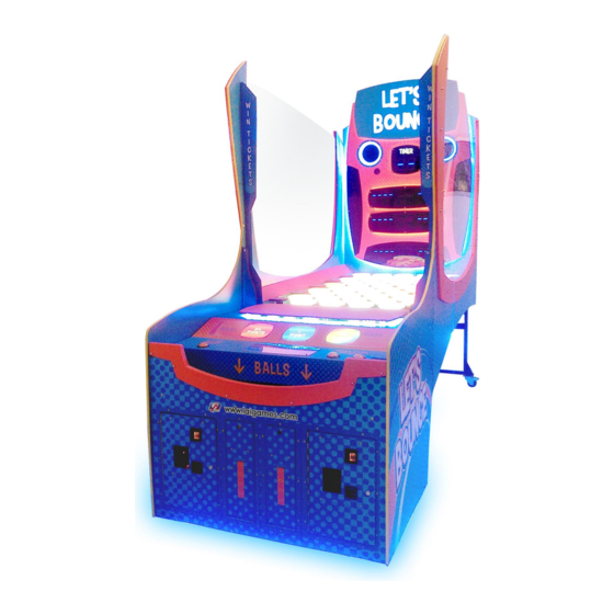
INTRODUCTION Congratulations on your purchase of Let’s Bounce by LAI Games. We hope you take the time to read this manual and learn about the many features and user-friendly adjustments that can be made to fine-tune the game for maximum earning potential. -
Page 10: Packing Detailed
PACKING DETAILED... -
Page 11: Assembly
ASSEMBLY PARTS DETAILED... -
Page 12: Assembly Steps
ASSEMBLY STEPS 1. Unlock the player panel with the key provided. 2. Lift the panel up until it stops. 3. Locate the mounting location for the bounce pad (7 holes). 4. Unlock the hex nut pictured. 5. Position the bounce pad correctly, and plug in the connector. - Page 13 6. Align the bounce pad studs to the holes and lock using the same nut that was unlocked in step 4. 7. Plug in the connector pictured. CAUTION: At least two people should be present to perform steps 8 to 10. 8.
- Page 14 10. Align the rear stand as shown, and lock it in place using the hex bolts from the previous step. 4 x hex bolts on the rear and 4 on each side. 11. Unlock the 4 hex bolts pictured. 12. Align the front cabinet section with the playfield.
- Page 15 CAUTION: At least two people should be present to perform steps 13 to 17. 13. Bring the playfield up against the front cabinet, and lift it slightly so the frame hooks on. 14. Lock the 4 x hex bolts that were unlocked in step 11. 15.
- Page 16 16. Position the right panel against the right side of the playfield (from the perspective of standing in front of the cabinet) and lock it in place using 6 x M6 screws. 17. Position the left panel against the left side of the playfield and lock it in place using 6 x M6 screws.
- Page 17 18. Position the header against the backboard, and plug in the connector shown. 19. Hold the header in position and lock in 4 x M6 screws. 20. Position the backboard against the rear of the playfield. 21. Sit the backboard on the frame and lock it in place using 8 x M6 screws along the bottom and 5 x M6 screws along both the left and right side (10 x screws total).
- Page 18 22. Ensure all the screws from the previous step are tightened, and plug in the 3 connectors shown. 23. Power on the game and ensure that all lights and sensors are functional. To access PCB fuses and wiring, remove the left panel, which was attached in step 17. Access is shown below. 24.
- Page 19 25. Lift the player panel, and attach the side acrylic with 4 x M4 screws. 26. Close the player panel and install the remaining 3 x M4 screws. 27. Repeat steps 25 and 26 for the acrylic sheet on the opposite side. 28.
-
Page 20: Gameplay And Modes
GAMEPLAY AND MODES OBJECTIVE At the start of the game, the Let’s Bounce playfield is made up of all orange tiles. Each tile awards points and turns blue after being hit. Orange tiles award more points when hit than blue. The player is given a set number of ping pong balls and must clear all the orange tiles from the playfield in the allocated time frame. -
Page 21: Attract Mode
ATTRACT MODE Attract mode provides a visual and audio display while the game is not being played. PLAY MODE Let’s Bounce has two play modes. The standard Coin Play mode, where a coin or coins are inserted, or Free Play mode, where no coins are necessary. COIN PLAY Coin Play mode is entered from Attract mode, by inserting coins in any of the two coin slots on the front of the machine cabinet, then following the instructions in the “How to Play”... -
Page 22: Operation
OPERATION GAME SETTINGS Coin 1 Coins per Credit Default 1, Adjustable 1 – 20 Sets the number of coins that need to be inserted in exchange for each game credit. Coin 1 Games per Credit Default 1, Adjustable 1 – 20 Sets the number of games granted for each credit. - Page 23 Coin 2 Multi Bonus Credits Default Off, Adjustable On / Off Turn on the first stage of bonus credits for coin mech 2. Turning this setting on, will activate settings 6-1 to 6-6. Coin 2, Stage 1, Number of Coins 6.1.
- Page 24 Prize Type Default Ticket, Adjustable Off / Ticket / Coupon Defines the type of prize given to the player. This only affects how the jackpot number and tickets owing number is displayed. If set to "off" then no prize is paid out. If set to "tickets"...
-
Page 25: Audits
AUDITS Total Coins 1 Shows the number of coins inserted on COIN1 input. Total Coins 2 Shows the number of coins inserted on COIN2 input. Total Service Credits Shows the number of times the service button was used to issue 1 credit to the game. Single Player Games Shows the total number of single player games played. -
Page 26: Input And Output Tests
INPUT AND OUTPUT TESTS OUTPUT TESTS All Outputs Flash all lamps, run playfield colors, 7 segment displays and player panel button lamps. Tiles Flash all playfield tile lights in order of tile 1 to 45. Score Count all seven segment displays from 0000 – 9999. Lights Flash the player one, player two, player panel buttons, round, score, clear and winner lamps. -
Page 27: Online Tiles
ONLINE TILES This menu can be used to set tiles to “offline,” meaning they do not need to be hit by the player to clear the playfield. A maximum of 10 tiles can be set as offline at any one time. When the first online tile is hit at the start of the game, it will simulate all the offline tiles being hit as well. -
Page 28: Errors
ERRORS Name Cause Solution Refill the ticket mechs and ensure there is no jam. Restart the machine. Enter Error menu in the operator menu. Select Error Ticket. The The game has run out of tickets or Error ticket 1 LCD will display Error Ticket – if there is a jam on ticket mech 1 Clear Ticket. -
Page 29: Hard Errors
HARD ERRORS This category of errors is used to identify specific errors serious enough that gameplay must be stopped, either to prevent damage to the machine or because it would result in a negative gameplay experience for the player. When a hard error is triggered, the error name is still displayed on the credit display, in addition to the words “hard error.”... - Page 30 The CPU cannot read or write Clear the error by viewing it in to its on-board EEPROM the errors menu and pressing program settings or is the right button. PSet Error receiving errors during If the error still occurs, the IC is communication with the faulty and needs to be EEPROM.
-
Page 31: Section A: Service Instructions
SECTION A: SERVICE INSTRUCTIONS NOTE: Be sure to read the following carefully before servicing the machine LOCATING AND ACCESSING PARTS The following pictures identify the location of the main serviceable items. CABINET FRONT 1. Header 2. Backboard 3. Playfield 4. Bounce pad 5. -
Page 32: Backboard
BACKBOARD 10 11 12 1. Speakers 2. Timer display lamp 3. Player 1 and 2 lamps 4. Player 1 and 2 round 1 score lamps 5. Player 1 and 2 round 1 clear lamps 6. Player 1 and 2 round 2 score lamps 7. -
Page 33: Player Panel
PLAYER PANEL 1. Bounce pad 2. End turn button 3. Single player button 4. Double player button 5. Credit display CABINET INNER 1. FB106 Sound Board 2. FB216 Game Control PCB 1. Ball lifter 2. FB86 Sensor PCB... -
Page 34: Cabinet Rear
1. Ball gate sensor – player 2. Ball gate sensor – home 3. Ball gate sensor - return CABINET REAR 1. FB63 display PCB 2. Lightboxes / lamps x12 3. Speaker crossover 4. Woofer speaker 5. Tweeter speaker 6. FB44 display PCB x6... -
Page 35: Cabinet Side
CABINET SIDE 1. FB214 Fuse PCB x5 (behind side panel) OPERATOR PANEL / SERVICE CONTROLS 1. Up button 2. Back / service button 3. Test / enter button 4. Down button 5. Volume control 6. Utility button 7. Coin 1 counter 8. -
Page 36: Accessing The Playfield
ACCESSING THE PLAYFIELD On newer models of Let’s Bounce the underside of the playfield is split into three panels, allowing easy access to the bottom of the playfield for maintenance purposes. If your unit doesn’t have three visible panels underneath it, please disregard this section. - Page 37 1. Identify the panel you want to remove and remove 4 x M4 x10 screws and washers per panel, as shown below 2. After removing the screws, follow the sequence below – lift, pull, then tilt – to remove the panel...
-
Page 38: Parts Description
PARTS DESCRIPTION HEADER DISPLAY The header is a static sign illuminated by LED strip lighting. BACKBOARD The backboard at the rear of the game mounts the speakers, FB63 timer display, FB44 score displays, and LED strip lamps. All components are accessible by removing the guards behind the backboard. SPEAKERS Two component speakers are wired to the left and right outputs from the FB106 sound board. - Page 39 DIP SWITCH ADDRESSING Addresses are set via DIP switches using binary coding. Patterns are shown below: Do not use address 0. ADDRESS...
-
Page 40: Counters
COUNTERS Counters will increment for each coin inserted and each ticket paid out. Counters are under firmware control and are not directly connected to the mechanisms. BUTTONS Press the green SERVICE/BACK button to issue a service credit from attract mode. Press and hold the green SERVICE/BACK button to enter temporary Free Play Mode. -
Page 41: Power Inlet/Mains Switch
All button lamps are 12VDC T10 LED or equivalent. All Playfield tile lights are FB205 PCBs. All remaining lighting is RGB LED strip. Contact your nearest LAI Games office for replacement LED strip to ensure color is matched. MAINTENANCE EXTERIOR •... -
Page 42: Fb216 Update Procedure
FB216 UPDATE PROCEDURE TOOLS REQUIRED • 1 x USB – TTL Serial Adapter with Connector Harness • 1 x PC or Laptop with USB Port running a Windows OS (will be connected to game during the update, so must be portable) •... -
Page 43: Procedure
PROCEDURE 1. Switch off the game that is being updated 2. Access the required service area and locate the PCB (refer to Locating and Accessing parts – Cabinet Inner for assistance in locating FB216) 3. Place the PC near the PCB, and connect them using the USB – TTL serial adapter cable, from the USB port on the PCB, to the J5 programming port on the PCB 4. - Page 44 6. For the Port Name setting, open the drop-down menu and select the only COM port available (COM number is automatic and can vary). If you’re unable to proceed to the next step when pressing next, restart the PC and try again. 7.
- Page 45 9. Press Next 10. Ensure that the target field correctly reads “STM32F4_05_07_15_17_1024K” 11. Press Next 12. Select “Download to device” on the left 13. Click the “…” button on the right hand side of the window, and navigate to and select the HEX file 14.
- Page 46 16. Press Next 17. Above the progress bar, the text will progress from “Downloading,” to “Verifying,” to “Success” 18. Once the progress bar is green and states “Download operation completed successfully,” press Close to finish 19. Turn off the game 20.
-
Page 47: Troubleshooting
TROUBLESHOOTING NO COM PORT SELECTABLE FROM DROP DOWN If you’re up to step 6, and there are no options to select a port from the drop-down menu, the PC is not able to communicate with the PCB 1. Ensure the game is powered on, and the PCB has power – verify that the heartbeat LED (shown below) is flashing to ensure that the PCB has power 2. -
Page 49: Section B: Technical Details
SECTION B: TECHNICAL DETAILS WARNING: Always turn OFF mains power and unplug the game before cleaning the interior of the machine. Always after cleaning the cabinet interior, check all harness connectors and restore all loose or WARNING: It is advised that anybody using SECTION B for repairing or modifying any of the interrupted connections. -
Page 50: Coin Options Reference Guide
PIN7 = GND PIN8 = COIN2 input PIN9 = 12VDC Contact your nearest LAI Games distributor for harnessing to suit different coin comparators and bill acceptors. UNIVERSAL CARD LINK CONNECTION A 9 pin Universal Card Link connector exists on the operator panel inside the coin door. -
Page 51: Ticket Mechanisms
Pin 6. Ticket Meter- is connected to the Ticket 1 Meter output from the game PCB and can be used by card systems for monitoring purposes. Pin 7. Empty Pin 8. Empty Pin 9. Ground- is connected to the common Ground connection, the same ground as the Game PCB. TICKET MECHANISMS 2 x ticket mechs can be fitted inside the ticket doors. -
Page 71: Mechanical Illustrations
MECHANICAL ILLUSTRATIONS MAIN ASSEMBLY... -
Page 72: Front Panel
FRONT PANEL... -
Page 73: Panel Door And Base Front Panel
PANEL DOOR AND BASE FRONT PANEL... -
Page 74: Coin Door And Ticket Door
COIN DOOR AND TICKET DOOR... -
Page 75: Coin Plate With Dba And Cash Box
COIN PLATE WITH DBA AND CASH BOX... -
Page 76: Operator Panel And Power Supply
OPERATOR PANEL AND POWER SUPPLY... -
Page 77: Player Panel
PLAYER PANEL... -
Page 78: Right And Left Player Panel Stopper
RIGHT AND LEFT PLAYER PANEL STOPPER... -
Page 79: Ball Gate And Db Box
BALL GATE AND DB BOX... -
Page 80: Ball Gate Motor And Display Sign
BALL GATE MOTOR AND DISPLAY SIGN... -
Page 81: Ball Lifter And Ball Hopper Chute
BALL LIFTER AND BALL HOPPER CHUTE... -
Page 82: Display Panel And Base Display Panel
DISPLAY PANEL AND BASE DISPLAY PANEL... -
Page 83: Base Score Panel
BASE SCORE PANEL... -
Page 84: Board Display Round 1 And Board Display Round 2
BOARD DISPLAY ROUND 1 AND BOARD DISPLAY ROUND 2... -
Page 85: Right And Left Side Walls
RIGHT AND LEFT SIDE WALLS... -
Page 86: Main Playfield
MAIN PLAYFIELD... -
Page 87: Peg Assembly
PEG ASSEMBLY... - Page 88 LAI Games shall have no liability related to such improper and unauthorized use and/or operation of the hardware and licensed software, and Operator shall indemnify, defend, and hold LAI Games harmless for any claim or cause of action brought against LAI Games arising from Operator’s or Operator’s representative’s improper and unauthorized use and/or operation of the hardware and licensed software.
- Page 89 WARRANTY LAI Games warrants its manufactured products for a period of 3 months inclusive of parts and labor from the date of sale. LAI Games exclusive obligation is to repair any item with any defects as a result of faulty workmanship or materials, providing the defective item or items of equipment are returned to the LAI Games distributor from which the machine was purchased.
- Page 90 Contact Us sales@laigames.com Sales and Enquiries: support@laigames.com Technical Support: www.laigames.com Website: For your nearest LAI Games Distributor, visit our web site at www.laigames.com...
Need help?
Do you have a question about the Let’s Bounce and is the answer not in the manual?
Questions and answers