Table of Contents
Advertisement
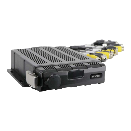
DV426/DV426-4G
4 Channel DVR Black Box Recorder
with WiFi, GPS & SATA SSD
SPECIFICATIONS
- Record Type
- 4G:
- GPS:
- WiFi:
- Vehicle Tracking:
- Max Resolution:
- Real Time Recording:
- G-Sensor:
- Motion Detection:
- AV Output:
- Monitor View:
- Video Compression:
- Reverse Camera Compatible:
- Camera Connection:
- Lockable Storage:
- Operating Voltage:
- Alarm Inputs:
- Alarm Outputs:
- Ignition Signal:
- Speed Signal:
- Timer Recording:
- Adjustable Frame Rate & Bit Rate: Yes
- User Password Protection:
- Operating Temperature:
- Power Consumption:
- Dimensions:
- Includes:
Quad
DV426-4G Only
Yes
Yes
Yes
1920 x 1080 (100FPS)
Yes - Auto or Scheduled
Yes
Yes
VGA, CVBS (RCA Adaptor Included)
Normal/Mirror Image Selectable
H.264 for High Quality Video
Yes
4 x 4-Pin
Yes - 1 x 2.5" SATA SSD (Not Inc), 1 x 128GB SD Card (Not Inc)
9 to 36V
6 CH
2 CH
Yes
Yes
Yes
Yes
-20°C to 70°C
15W (Working)
183 x 38 x 148mm
Keys, Antenna Kit, Remote Control, Power Cable, Alarm Cable, USB Cable
1
INSTRUCTION MANUAL
2
YEAR WARRANTY
Advertisement
Table of Contents

Related Manuals for Axis DV426


Summary of Contents for Axis DV426
- Page 1 4 Channel DVR Black Box Recorder YEAR WARRANTY with WiFi, GPS & SATA SSD SPECIFICATIONS - Record Type Quad - 4G: DV426-4G Only - GPS: - WiFi: - Vehicle Tracking: - Max Resolution: 1920 x 1080 (100FPS) - Real Time Recording:...
-
Page 2: Specifications
1. Specifications 4CH HD DVR Operating system Linux Operating interface Graphical menu operation interface(OSD) System Video permission Administrator & user setting Video input 4 x 1080P analog high definition CVBS output 1CH 6pin aviation connector output PAL/NSTC VGA output 1CH VGA output, 1080P Video HDMI output NULL... - Page 3 WIFI optional WIFI hotspot/AP optional Internal or external GPS/GLONASS module, coordinate/speed can be encoded in video stream and uploaded to server by wireless communication G-Sensor Available six axis sensor /Gyroscope Windows client Available Software iOS client Available Web portal Available...
- Page 4 2. Precautions 1、 Motion detection function is set to OFF by default. Alarm files will be created when there’s motion detected when set ON.G-sensor recording is recommended to set ON during driving for emergency recording use. G-sensor level is optional. 2、If the DVR can not boot up, try to remove all storage disks from the DVR, and then restart the DVR to check whether it can boot normally or not.
-
Page 5: Main Features
3. Main Features Appearance Smaller than the previous models. Controlled by touch screen All settings and operations could be done through the monitor if connected with the suggested touch screen. Video and Audio 4 channels * 1080p, 4 video inputs with audio ... - Page 6 Support USB disk or USB hard disk to backup copy of recording files. Network Support LAN, WI-FI, 2G/3G / 4G, automatic network switching; LAN / Wi-Fi / Cellular connection (default priority: LAN > Wi-Fi > Cellular); auto switch to LAN / Wi-Fi connection when available to save Cellular traffic.
-
Page 7: Wiring Diagram
4. Wiring Diagram BLANK 5. Connection - Front Panel... -
Page 8: Electronic Lock
① LED Indicators ⑤ IR R eceiver ② E lectronic lock ⑥ SD Card Slot ⑦ SSD Slot ③ Front Cover Buckle ④ USB3.0 Interface ⑧ SIM Card Slot 5.1 LED NULL 5.2 Electronic Lock Close the front cover and turn the groove by the key to the icon “off”, so as to ... -
Page 9: Sd Card Slot
5.5 SSD card slot Hard disk Type: SSD (Max. capacity: 2T ) Size: 2.5 inches(70*100*7mm). 5.4 SD card slot SD card type: The maximum capacity of each card is 128G. Insert、remove SD card Step 1: Use the key to unlock and open front plate Step 2: Insert SD card to SD card slot... -
Page 10: Back Plate
Step 3: Close the front plate and use the key to lock 5.6 USB Slot USB 2.0/3.0, Max. Capacity 2T 6. Back Plate ③ Wi-Fi Connector ① Cellular Connector, TX/ R X ② Cellular Diversity Connector, Rx ④ GPS Connector... - Page 11 6.1 Power power input 9 PIN Avation female connect to 9 PIN Avation male on the DVR Connection Connect ignition wire to yellow ACC wire of DVR, battery Positive to V+(Red wire), Negative to GND(black wire) 6.2 Camera(AVIN 1~4 ) See below 4 cameras diagram.
-
Page 12: Lcd Monitor
Connect No.1 camera to AVIN1 4PIN Aviation male Connect No.2 camera to AVIN2 4PIN Aviation male Connect No.3 camera to AVIN3 4PIN Aviation male Connect No.4 camera to AVIN4 4PIN Aviation male 6.3 LCD monitor EDID (Extended Display Identification Data) is automatically acquired when power is turned on.Output resolution of the LCD monitor can be selected. - Page 14 The parameter list of 7/10 inches HD monitor Description HD 10.1"Color monitor HD 7"Color monitor Features used for HD DVR used for HD DVR Resolution 1024 x 600 (RGB) 1024 x 600 (RGB) Maximum Number of Cameras Audio input Audio output (loudspeaker) HDMI input VGA input...
-
Page 15: Alarm Interface
c. Disk file system exception : one long beep and three short beeps d. If disks are normal but the alarm video files are full : two short beeps and one short beep e. No camera input: two short beeps , and two short beeps after a second f. - Page 16 10 PIN Colour pink blue gray white purple green yellow black black Alarm Alarm Alarm_in Alarm_in Alarm_in Alarm_in Alarm_in Alarm_in Definition out2 out1 There are 6 alarm inputs including alarm inputs 1 ~ 4, reversal input, brake input, which can trigger the alarm recording. . Cursor will be displayed when the alarm input channel is working.
-
Page 17: Panic Button (Optional)
6 Panic button (Optional) Overview The LEDs are used to show the device’s working status. But when the device is installed in the vehicle, it is not easy to check the LED on the front panel. Each of the LED indicates the corresponding status. - Page 18 8 PIN female head connect to 8 PIN male head(RS232&RS485) on the DVR Color Any of the cameras have no VLoss Amber Normal Operation signal alarm Soft Recording Normal driving Not recording green Amber GPS cannot latch Normal Operation Storage Alarm or no Normal Operation Storage device...
-
Page 19: Built-In Gps Antenna
If the alarm recording was triggered, there will be an alarm sign on the screen, as shown below: 6.7 Built-in GPS antenna Built-in GPS antenna socket and GPS antenna, as shown in the picture. -
Page 20: Menu Introduction
7. The Menu 7.1 Menu Introduction Touch [MENU] on the remote or touch the bottom area, the LOGIN page will be displayed on the LCD screen. The Shortcut Menu will be displayed after login. If you press [MENU] on the remote or Touch the bottom area again, the Main Menu will be displayed. ①... - Page 21 ⑤ Electronic Lock Sign Lock indicator turns red when electronic lock is locked and front cover is closed. Electronic lock is different from menu lock. ⑥ GPS Sign The GPS Sign will be flashing when connecting. It will be always ON if successfully connected.
- Page 22 DVR supports two kinds of permissions: admin permissions and guest permissions User permissions list User Name admin guest Password Modification Initial Password Enter the menu of Enter all menus Playback,Display mode Permissions switching and Volume User name cannot be changed, but user password is changeable. (See the ...
- Page 23 7.3 Keyboard Operation Instructions Switch letter case : :Exit the keyboard interface :Delete the input letters...
- Page 24 :Switch to the numeric interface :Switch to the English alphabet interface :Switch to the special character interface Character Switching Instructions...
- Page 26 Letter Case Switching Instructions 7.4 Manually Record Touch this icon to start or stop recording. Video files can be found in the Normal list of Player menu. 7.5 Playback Video Playback button: Touch this icon to enter the calendar menu. Green marked date means it has recording files saved on that day.Select the date to enter the video file list, then select the file and touch Play icon to play video.
- Page 27 Specific operation sees below. Search by month : Search by year Normal: Normal recording list, including Normal Recording, Power on Recording, Schedule Recording Event: Alarm recording list, including alarm recording 1~6, Motion detection recording, G-sensor recording, Speed recording, Panic button recording Type Recording Time Control Mode View Position...
-
Page 28: Display Mode Switching
All: Select all video files in this page Exit: Exit : Volume adjusting button : Switch : Play the previous/next video : Pause/Resume playing : Hide the play menu. And press [Area 1] to display. : Exit playing 7.6 Log System memo checking, memo output 7.7 Display mode switching Mode switch button: Touch this icon to enter the Mode switch interface. - Page 29 :One-division mode of Camera Left (CH1) : One-division mode of Camera Right (CH2) : One-division mode of Camera Front (CH3) :One-division mode of Camera Back (CH4)
- Page 30 Three-division mode of Camera Left, Front and Back (CH1, CH3, CH4) Three-division mode of Camera Front, Back and Right (CH3, CH4, CH2) Three-division mode of Camera Front, Left and Right (CH3, CH1, CH2) Three-division mode of Camera Left, Right and Back (CH1, CH2, CH4) :Two-division mode of Camera Front and Back (CH3, CH4)
- Page 31 :Two-division mode of Camera Left and Right (CH1, CH2) :Four-division mode of Camera Left, Right, Front and Back (CH1, CH2, CH3, CH4) :Four-division mode of Camera Left, Front, Back and Right (CH1, CH3, CH4, CH2) :Set the current selected mode as default. :Exit.
- Page 32 7.9 Disk Disk management button: Touch the disk management icon, then you can view the status of SSD, SD card and USB.
- Page 33 ① Disk type ② ALL:The total capacity of disk,free:The remaining capacity of disk If ALL shows 0.00MB, it means that DVR does not have access to this type of disk ③ Green area shows the capacity of all the recording files in the Normal list Red area shows the capacity of all the recording files in the Event list Blue area shows the capacity of all the pictures in the Capture list Yellow area shows the capacity of all the other files except those above...
- Page 34 All recordings are set off The FTP button is set off ⑤ It shows that the disk needs to be formatted before use. All new disks must be formatted before use. ⑥If SSD Out is ON, the recording files in the disks can be exported to computer via USB cable.
-
Page 35: Record Setup
8. Record Setup 8.1 Power On Rec The DVR will start recording after power on when 'Power On Rec’ is set to ON. Default is ON. 8.2 Cyclic Rec New video files will overwrite the previous ones when disk is full if setting the Cyclic Rec ON. -
Page 36: Video Quality
Event Rec.:Event recording type includes motion detection triggered alarm, G-sensor triggered alarm, alarm 1 ~ 6 triggered alarm ,Panic button triggered alarm and over speed alarm. If the Event Rec is ON and corresponding alarm parameters are set, event recording will be activated when the events above are triggered. If the Event Rec is OFF, event recording will not be activated even if event is triggered. - Page 37 The main stream is used for video storage. The sub stream is used for video backup and network transmission. ① R esolution There are 5 levels of resolution in main stream menu for option,1080P, 720P, D1 (PAL), D1 (NTSC),AUTO. And 3 kinds of optional resolution in Sub stream menu, CIF (PAL), CIF (NTSC),AUTO.
-
Page 38: Record Channel
Bit rate Main stream Sub stream If 1080P camera is connected, the bit rate will be 4Mbps . If 720P Whatever cameras are connected, the AUTO camera, 2Mbps. And if D1 camera, bit rate will always be 64Kbps. 1Mbps. ③ Fram e rate There are 5 levels of frame rates in Main stream and Sub stream menu for option : 28fps, 25fps, 20fps, 15fps, 10fps, 5fps. -
Page 39: Event Duration
After set on recording (including all types) and selecting the recording channels, the corresponding channels will be recorded. If turning off a video channel, the corresponding channel will not be recorded even if the recording function is on. Note: The config is for normal recording, but not for event recording. Event recording will record all channels by default and it can’t be changed. -
Page 40: G-Sensor Sensitivity
For this kind of event record or alarm record, the pre-record time will be set as 15s and the post-event time is configured by Event Through the nine-axis G-sensor, DVR can measure the acceleration and angular Duration above. - Page 41 (abs(X), abs(Y) and abs(Z) are the datas of the acceleration sensor on X-axis, Y-axis and Z-axis) After the setting of threshold and duration is finished, the installation settings and the correction of the sensor will be needed. By default, * If the vehicle accelerates continuously to the +X-axis while driving, and the value of Acce exceeds the threshold for 100ms, the Acceleration Alarm will be triggered.
- Page 42 (the side without lock ) Y-axis The X-axis is the front of the DVR(the side with LED). The Y-axis is the left side of the DVR(the side without lock). And the Z-axis is the vertical upward direction. The coodinate system of the vehicle is shown as below:...
- Page 43 Forward is set to be -Z, and Left is set to be +Y, it means that the forward direction of the DVR is the direction of -Z-axis and the direction of +Y-axis is on the left of the vehicle while the vehicle is driving , which means that the DVR is fixed vertically in the vehicle and the bottom of the DVR is facing the front of the vehicle.
-
Page 44: Camera Display Setting
8.10 File Type File format setting. 9. Display 9.1 Camera display setting Camera: Parameter setting for each corresponding camera channel: including brightness, contrast, saturation and hue.All values for default setting are 50. To change the value, drag the bar to left or right to decrease or increase. -
Page 45: Camera Name Setting
9.2 Camera name setting Camera name: Set a camera name, then the camera name will be displayed at the bottom of the camera display. Touch the camera name on the menu, then a keyboard menu will pop up to input a new camera name. -
Page 46: System Language Setting
9.3 System Language setting Menu Language for option: English, Russian. 9.4 Audio Out Audio out: Select the audio output channel in split mode. -
Page 47: Osd Display Setting
9.5 OSD display setting OSD configuration: Select whether to display time, channel name, license plate in video or not (if On, all the information above will be written in video and can be displayed in playback) 9.6 Menu on Menu on: Set duration of menu display... - Page 48 Menu on: Menu on duration can be set to 30s, 60s, 120s and Always. When it is set to 30s, 60s, 120s, it means that the menu will be hidden if there is no operation in 30s, 60s or 120s after it is open. When it is set to Always, the menu will always be there. Please be noted that if enter the menu, the recording will stop.
- Page 49 9.8 GPS GPS: When the GPS antenna is properly installed, latitude, longitude and speed will be recorded into video files. The menu provides GPS information of latitude / longitude, detectable satellites, accessible satellite etc. Mode:GPS status. It will be shown as below: Connected ...
- Page 50 9.9 Mirror ON: Turn on Mirror function OFF: Turn off Mirror function 10. Network...
- Page 51 10.1 LAN port and server setting DHCP: Dynamic Host Configuration Protocol. To set it on stands for dynamic IPand off, for static IP. Static IP must be manually input with IP address, mask and gateway. MAC address can be automatically assigned or revised. Enable LAN ...
-
Page 52: Wi-Fi Network Setup And Server Setup
Step 6: Input LAN Server IP and Port. Touch OK to save the setting. 10.2 Wi-Fi network setup and server setup Wi-Fi: Wi-Fi on/off DHCP: Dynamic Host Configuration Protocol. To set it on stands for dynamic IPand off, for static IP. Static IP must be manually input with IP address, mask and gateway. MAC address can be automatically assigned or revised. - Page 53 Enable Wi-Fi Step 1: Wi-Fi hot spot available Step 2: Connect the Wi-Fi antenna at connector ⑥ of device rear panel Step 3: Go to Wi-Fi setup interface, set Wi-Fi to ON and open the dynamic IP button. Step 4: Touch SSID sub-menu and the Wi-Fi hot spot shows up. Select the hot spot to connect and input password.
- Page 54 10.3 2G/3G/4G control and its network setup Cellular: Cellular is on, meaning that 2G/3G/4G is on. Network Standard: WCDMA by default. APN &Access Number: Normally, the user doesn’t need to input user name and password for APN and Access number. The default setting is available. If it can’t communicate with the network under the default setting, please consult your local network carrier.
- Page 55 Username &Password: Reversed. OK: Save the settings and quit. Cancel: Cancel the settings and quit. Enable 2G/3G/4G step 1: DVR can search 2G/3G/4G signal locally. Step 2: Connect the 2G/3G/4G antenna at connector ⑤of DVR rear panel. step 3: Open the DVR front housing and insert the 2G/3G/4G SIM card. step 4: Go to Cellular setup interface and set Cellular to ON.
-
Page 56: Network Status
10.4 Network Status Network Status: Users can check information such as LAN IP address、 MAC address、 Wi-Fi network status、 Wi-Fi IP address、 Wi-Fi signal strength、 2G/3G/4G network status、2G/3G/4G signal strength, and Server status. Additionally, users can verify whether network connection is successful or not. LAN IP: Refers to the static IP set on Network-LAN page or the dynamic IP which is obtained automatically. - Page 57 Wi-Fi status: Wi-Fi status will be shown as below: CONNECT SUCCESS GETIP ERROR Cellular : The on/off status of cellular acquired from Network-cellular page Module: Display the Cellular module brand Wireless RSSI: 2G/3G/4G signal strength icon Wireless Type: Display the types of 2G/3G/4G module, the parameters and the corresponding types are shown as follows 2G: Receive 2G signal 3G: Receive 3G signal...
- Page 58 10.6 FTP Username/Port/Password: Correct Username / Port / Password of the FTP server must be filled in. FTP: ON/OFF...
- Page 59 Normal File: Two states, OFF and ON OFF: Upload alarm files only ON: Upload all files (including Normal Files) Cellular: Two states, OFF and ON OFF: Files are not allowed to be uploaded when Cellular is connected to the Internet ...
- Page 60 11. System...
-
Page 61: Log In Setup
11.1 Log in setup Set user name and password for booting up. The initial password is 123. 11.2 License plate number setup Input license plate number... - Page 62 11.3 System time setup Format Setup:...
- Page 63 Go to “System - Date&Time - Format_Setup” page. ① Time Zone: time zone setting. ②Date Format: set the format of date. ③24 Hour: if it is ON, time format will be displayed in 24-hour system. If OFF, in 12-hour system. Time Snyc Setup:...
- Page 64 Go to “System - Date&Time - Time Sync_Setup” page. ① GPS: set GPS to ON/OFF ②NTP: set NTP to ON/OFF ③NTP Server: show the URL of the NTP Server DST Setup:...
-
Page 65: Scheduled Recording
Go to “System - Date&Time - DST_Setup” page. ① Enable: Set DCT setting to ON/OFF ②Offset: Adjust the offset after enabling DST ③Mode: Select the mode of DST(setup DST according to week or date) ④Start: Set start time of DST ⑤End: Set end time of DST 11.4 Scheduled Recording... - Page 66 Enable: Set scheduled recording ON/OFF. Start: Set start time of scheduled recording. End: Set end time of scheduled recording. Week-day: Set scheduled recording by weekdays. Select the weekdays to set preset. Scheduled Recording: * Support up to four appointed tasks. The recording duration is counted in minutes.
-
Page 67: Acc Settings
Buzzer: Set the buzzer to ON/OFF. Duration: Set the duration time of the buzzer. 11.6 ACC settings... -
Page 68: Alarm Information Setting
Current vol.: Voltage of the working DVR Shutdown vol.: Shutdown voltage function will work after DVR starts working for 1mins. DVR will shut down automaoi.iktically if current voltage is lower than shutdown voltage, and it will reboot only when the voltage is above the value. ACC Duration: DVR will continue recording for a few seconds after ACC is disconnected. - Page 69 Priority: Set priorities for Alarm1~Alarm4, Reverse, Brake, Left, and Right. When different types of alarm are triggered at the same time, alarms with the highest priority will work first. Trigger Level: There are 3 options of Trigger Level. The options “Low” and ” High” are used for turning on alarm function.
- Page 70 ①Camera name of the alarm-triggered channel. ②Press this button to turn on/off curser. ③Line selecting: There are five lines to be selected, Line U(up), Line D(down), Line L(left), Line R(right) and ALL. The button is green if selected. You can use remote control to operate.
- Page 71 : Press it, then the priority value of the selected alarm will be added by 1. The bigger the value is, the lower the priority will be. : Press it, then the priority value of the selected alarm will be reduced by 1. The smaller the value is, the higher the priority will be.
- Page 72 Step 3: When “Update success!” is shown on the DVR monitor, the DVR will reboot automatically.
- Page 73 Step 4: After rebooting, please check if the version is the same as the one you copy into “upgrade” folder. Please go to Menu -> System -> Info to check it. For batch upgrade As the upgrade package will be deleted after the upgrade process is done on device, so if you need to upgrade more than one device, please carry out as follows: Step 1: Rename the package “dvxxx_upgrade_201xxxxxxxxx”...
- Page 74 Step 4: After When “Update success!” shows, unplug the USB disk or SD card with upgrade package, then DVR will reboot automatically.
- Page 75 Note: If using “dvxxx_upgrade_never_rename” package to upgrade, we must unplug the USB disk or SD card when “update success!” is shown on the screen, or else the DVR will go into infinite loop of upgrade and will not boot up. SOLUTION: Unplug the USB disk or SD card with upgrade package, and then DVR will stop the upgrade process and boot up successfully.
- Page 76 11.9 Configuration Configuration Import: Import the configuration information from USB memory flash devices. Configuration Export: Export Log to USB memory flash devices. Factory Default: Press RESET to restore factory settings.
-
Page 77: System Info
11.10 System Info System Info:Software version number. - Page 78 12. FAQ 1) The system can’t start up? Check power connection. Please follow the steps below to check the power connection: Check the input power: if the power wire is connected correctly, if the ground wire is connected to the battery, and if the fuse on the power wire is in good condition.
- Page 79 13. APPENDIX APPENDIXⅠ:Abbreviation & Description Rec. Record Secure Digital Memory Card G-sensor Accelerometer sensor Universal Serial Bus 44PIN connector, A/V Input, Global Positioning System DB44 Output.IO/ALARM Output 26PIN connector, Alarm Wi-Fi WIreless-FIdelity DB26 Input/RS232/RS485 Camera Alarm Audio Video Interleaved VLOSS Video Loss On-Screen Display COMM...
- Page 80 APPENDIXⅡ:Accessories NULL...
- Page 81 APPENDIXⅢ :Compatibility Storage List SATA 3.0 SSD Test Read Test Write Brand SIZE Flash Model Name Capacity Interface Speed Speed Name (inch) Type (MB/s) (MB/s) Toshiba HDTS812 120G SATA3 98.0 119.7 MTFDDAK960 Micron 960G SATA3 67.4 73.8 Samsung MZ-750120 120G SATA3 94.6...
- Page 82 Test Read/Write, THN-N302R032 SDHC Standard TOSHIBA 10.1 Update software, HotPlug Test Read/Write, THN-N302R064 SDHC Standard TOSHIBA Update software, HotPlug Test Read/Write, THN-N302R012 SDHC Standard TOSHIBA Update software, 80C4 HotPlug Test Read/Write, Transcend 64GB SDXC Standard Transcend 10.6 Update software, UHS-I U3 UHS-I HotPlug Test Read/Write,...
- Page 84 DV426/DV426-4G...
Need help?
Do you have a question about the DV426 and is the answer not in the manual?
Questions and answers
How to format ssd 2t drive
To format a 2TB SSD drive for the Axis DV426, follow these steps:
1. Insert the SSD into the DVR.
2. Ensure that:
- There is a disk in the slot.
- All recordings are turned off.
- The FTP button is turned off.
3. Access the disk management menu.
4. Select the SSD and choose the format option.
5. A dialog box will appear stating, “Disk data will be deleted! Continue?”
6. Press OK to start formatting.
7. Wait for the process to complete.
Note: All new disks must be formatted before use. If formatting fails, check the disk connection and settings.
This answer is automatically generated