Axis ME-01 Mounting Manual
Hide thumbs
Also See for ME-01:
- Engineering documentation (50 pages) ,
- Engineering documentation (69 pages)
Table of Contents
Advertisement
Quick Links
Advertisement
Table of Contents

Related Manuals for Axis ME-01


Summary of Contents for Axis ME-01
- Page 1 MOUNTING GUIDE ME-01 indicator File: 2014-10-01 ME-01_mounting bE_bC0100 GB...
-
Page 2: Table Of Contents
OUNTING GUIDE Content: 1. Introduction ________________________________________________________________ 3 2. Connecting load cells _________________________________________________________ 4 3. General description of scale’s firmware __________________________________________ 8 3.1 Keys and meter indicators _________________________________________________________ 11 3.2 Scale programming sequence _______________________________________________________ 12 3.3 General rules during scale programming _____________________________________________ 12 4. -
Page 3: Introduction
OUNTING GUIDE 1. Introduction This manual describes AXIS meters: ME-01/A/LED ME-01/A/LCD ME-01/N/LED ME-01/N/LCD ME-01/N/25 (LED) ME-01/P/LCD ME-01/P/25 with bE0100 (LED version) and bC0199 (LCD version) firmware or later. Detailed description of meters and scales based on the meters way of working can be found in user manual of specific type of meter. -
Page 4: Connecting Load Cells
OUNTING GUIDE 2. Connecting load cells 2.1 Sensor selection General requirements for tensometric sensors (load cells): Max quantity of sensors 8 pcs Total impedance (all sensors) 40÷4000 Connecting sensors 4 or 6 wire system Maximal cable lenght to cable diameter 75 m/mm Sensor supply 5V (choper) - Page 5 OUNTING GUIDE ME-01/A … 4 wire connection scheme: When 6-wires connection of strain gauge transducers is used (REF+ and REF) cramps shown on the picture above should be soldered out from the main board (load cell wires are connected EXC+, EXC-, IN+,IN- and additionally...
- Page 6 OUNTING GUIDE Sensors check To check if tensometric sensors (load cells) are ok use Calib/Zero option. In zero option scale displays result in internal resolution (results directly from A/D converter). Input voltage range: 0Umax 0 ~160 000 internal division (on chart 160 000 is 100% of A/D range) A/D result range: Default Umax value is 10mV and can be changed to 20, 40 or 80mV.
- Page 7 To make GND connection use sensor’s factory GND connection or one of the wires that extend factory connection or additional wire. Stainless steel housing meters have special external GND clip. The connection should be made with thick wire. As a model look at AXIS constructions. 2.5 Connecting external devices...
-
Page 8: General Description Of Scale's Firmware
OUNTING GUIDE 3. General description of scale’s firmware The firmware consists part for USER (normal weighing, special functions) and for SERVICE (service menu functions). Service menu diagram: (Scale type) bA-... ( -2,-3,-3500,-400,-50,-6,-10,-15, out) BA series scales ModE SCALE BA/Y series scales bAY-... - Page 9 OUNTING GUIDE - band 868MHz turned on rF-868 Prt-rF - band 915MHz turned on rF-915 - band 433MHz turned on rF-433 - out - initial load value inscribing (starting zero) on_F ZEro - out - zero value inscribing CALIb ZEro - linearization of scale’s characteristic LINEAr - temperature compensation...
- Page 10 OUNTING GUIDE In further chapters of the manual, mainly service options are described. User options are described in user manual. Working mode settings and storing parameters can be performed by selection (activation) of proper functions in service menu. The settings are stored in internal memory (EEPROM). The process will be called scale programming (setting).
-
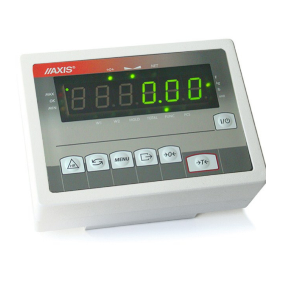
Page 11: Keys And Meter Indicators
OUNTING GUIDE 3.1 Keys and meter indicators Version with LED display: netto mass zero stabilization metrological weighing indicator indicator indicator data result Max= unit HOLD TOTAL FUNC scale keys - ON/OFF switch (standby), - tare set (entering package weight, subtracted from weighed mass), ... -
Page 12: Scale Programming Sequence
OUNTING GUIDE 3.2 Scale programming sequence After mechanical and electronic assembly to program the scale follow the sequence below. Information necessary for mechanical and electronic installation is described in chapter 2 and 3 and in DTR manual (delivered with the scale). 1. -
Page 13: Service Menu Description
OUNTING GUIDE 4. Service menu description Service menu (not available for user) consists options and functions set that decide about scale working mode. Service menu consists of following option catalogs: ModE – options connected with scale working mode On-F – user special functions CALIb –... -
Page 14: Special Functions (On_F)
OUNTING GUIDE rF – options for radio communication 4.2 Special functions (On_F) ZErO option is used to inscribe starting zero value (primary zero). Using this function is essential when additional construction elements are put on the pan e.g. container. Without inscribing correct value of start load „unLOAd” communicate appears. -
Page 15: Entering A Service Catalogue - Scale Decoding (Should Be Necessarily Done First)
OUNTING GUIDE 5.1 Entering a service catalogue – scale decoding (should be necessarily done first) press MENU key. Choose SEtuP and SErVICE Enter 6 digit access code 781213 by using keys: - 0 - changes value of displayed digit. - T... - Page 16 OUNTING GUIDE select ModE and SCALE option, select proper scale type: - initial selection – according to letter type – ex. for B2D scale (=BA2D) choose „bA-” - further selection – according to successive digits – ex. for B2D scale (=BA2D) choose „2” - final selection –...
- Page 17 OUNTING GUIDE choose (activate) legalized scale type (if needed) - tYP_LEG Not legal scale (nLEGAL) displaying last digit 0 key turned off During normal work (switch in standard position ) and during service work (switch in service position) in calibration option all sub-options are available.
-
Page 18: Sensitivity Calibration
OUNTING GUIDE Set-E - entering verification unit (e) in format as above, “current E value” – entering new value using keys as above, Out-E – leave without changes, E.g. for scale with verification unit of 0,2kg enter: 0.2 Set-d - select scale result rounding: 0(1), 2, 5,10 or 20, E.g. -
Page 19: Enter First Zero Value (Reference Zero)
OUNTING GUIDE - enter CAL-Pt and perform calibration with available quantity of calibratin standards of mass, - observe scale indication and replace standard of mass with product (ballast) with the same weight, again put on standards of mass. Having now bigger weight on scale use CAL-Pt function, etc. until You obtain weight equal to scale’s Max. -
Page 20: Linearity Calibration
OUNTING GUIDE Turn on and off the scale using I/ key, press and hold MENU, During C-2 display, after the sound signal release MENU key, choose options catalog CALIb and COMPt option, wait until the scale is stable and program version disappears. -
Page 21: Rs232 Interface Installation
OUNTING GUIDE 5.8 RS232 interface installation press MENU key, choose SEtuP and SErVICE choose options catalog ModE and Port-1 or Port-2 option, set wanted parameters, press MENU key in order to exit. Attention: Parameters transmission setting i salso possible using user special function rS. 5.9 Digital filters setting (connected with indication dynamics) 5.9.1 Setting initial filter AvEr_A and proper filter AvEr_b Averaging filter AvEr_A evaluates arithmetical average from measurements made by A/C transducer. -
Page 22: Rat_Stb Option
OUNTING GUIDE Value rAtIo _b – allowed difference of results getting out from filter. When allowed values are exceeded filter turns off. 5.9.2 rAt_Stb option Value of difference beetwen following indications, beyond this value indicator shows up. Way of setting similar to the way in 4.9.1. -
Page 23: Special Functions
OUNTING GUIDE 6. Special functions All scales, beside basic metrological functions like weighing and taring, are equipped with set of special functions. Basic set includes the following special functions: - activation of functions in menu (ACtIV), - autozeroing (AutotAr), - pieces counting (PCS), - change of mass unit (UnIt), - percent calculations (PErCEnt), - preparing recipes (rECIPE),... -
Page 24: Mechanics Description
The load cell is mounted to the scale base with two or four screws. The screw placed in the scale base in the pan clamp axis under the load cell is a main limiter protecting against overloading. -
Page 25: Limiters Adjusting
OUNTING GUIDE 7.2 Limiters adjusting View from down: View from side: Corner limiter 2 Central limiter 1 When the load cell is correctly mounted, adjust the overload limiter to the proper height. In scales with one central limiter only, the limiter is placed below the load cell. Place the max load on the pan and adjust the limiter so that there is 0.5mm space between the limiter and the load cell. -
Page 26: Disassembly And Assembly Of Scale Housing
OUNTING GUIDE 7.3 Disassembly and assembly of scale housing In order to dissasembly meter housing unscrew 4 hex tap bolts 1 visible from meter bottom. After opening the housing set up it like on the picture below in order to ease further manipulations during electronics repairment. During mounting pay attention on proper setting the seal 3, in case of damaging –... -
Page 27: Centricity Checking And Regulation
OUNTING GUIDE 7.4 Centricity checking and regulation To check non-centricity indications enable the last digit of the display (StAn-0 option) and follow the sequence below: 1. Place the weight of 1/3 of the Max load in the middle of the pan and tare the indication with T key. 2. -
Page 28: Common Scale Failures
OUNTING GUIDE 8. Common scale failures 8.1 Messages about errors and faults During normal work and during setting parameters of the scale by service pay attention to following text messages: Message Reason Recommendation Error of processor tests replace processor or main board (more than 20 s) Error of EEPROM tests replace EEPROM... -
Page 29: Most Frequent Faults
OUNTING GUIDE 8.2 Most frequent faults Defect Action description Display does not show any indications check if power supply is connected to the scale and power network 230V check power supply check display connection Unstable indication (frequent change of check contamination below the scale pan indications), check if the strain gauge does not rub check analog-digital transducer...
Need help?
Do you have a question about the ME-01 and is the answer not in the manual?
Questions and answers