
Related Manuals for powersoft Digimod 3004 PFC2


Summary of Contents for powersoft Digimod 3004 PFC2
- Page 1 Digimod 3004 PFC2 USER GUIDE ©2019 Powersoft Keep this manual DO000XYZ.00 Rev. 00 for future reference...
- Page 2 Data are subject to change without notice. For latest update please refer to the online version available on www.powersoft-audio.com.
-
Page 3: Table Of Contents
6. Electrostatic Discharge (ESD) viii 10 : 6.11. Control Board protection LEDs 10 : 7.LED chart 7. Digimod 3004 PFC2 10 : 7.1. Control Board LED chart 7 : 1.Welcome 10 : 7.2. Main Board LED chart 7 : 2.Unpacking & checking for shipping damage 12. - Page 4 Page intentionally left blank ii | Digimod 3004 PFC2 | User guide...
-
Page 5: Important Safety Instructions
8. Do not defeat the safety purpose of the polarized or grounding- Symbol for earth/ground connection. type plug. 9. Only use attachments/accessories specified by Powersoft. Symbol for conformity with Directive 2002/96/EC 10. Refer all servicing to qualified service personnel. Servicing is... -
Page 6: Importantes Instructions De Sécurité
LES BORNES D’ENCEINTES POURRAIENT ÊTRE DANGEREUX SI LA CONNEXION DE MODE PONT DU HAUT-PARLEUR EST UTILISÉ. ADOPTER DES TECHNIQUES CORRECTES DE CONNEXION ET D’ISOLEMENT LORSQUE LA CONNEXION EN MODE BRIDGE HAUT-PARLEUR EST UTILISÉ. iv | Digimod 3004 PFC2 | User guide... -
Page 7: Instrucciones De Seguridad Importantes
6. No bloquee las aberturas de ventilación. Realice la instalación de de operación o mantenimiento. acuerdo con las indicaciones de Powersoft. 7. No instale cerca ninguna fuente de calor como, por ejemplo, La marca CE indica el cumplimiento de la directiva radiadores, rejillas de calefacción, hornos u otros aparatos que... -
Page 8: Importanti Istruzioni Di Sicurezza
DIFFUSORI POTREBBERO ESSERE PERICOLOSI, SE VIENE UTILIZZATA LA CONNESSIONE IN MODALITÀ BRIDGE DEGLI ALTOPARLANTI. ADOTTARE LE CORRETTE TECNICHE DI CONNESSIONE E ISOLAMENTO QUANDO VIENE UTILIZZATA LA CONNESSIONE IN MODALITÀ BRIDGE DEGLI ALTOPARLANTI. vi | Digimod 3004 PFC2 | User guide... -
Page 9: Regulatory Information
The Waste Electrical and Electronic Equipment Directive (WEEE Directive) aims to minimise the impact of electrical and electronic goods on the en- vironment. Powersoft S.p.A. comply with the Directive 2002/96/EC and 2003/108/EC of the European Parliament on waste electrical finance the cost of treatment and recovery of electronic equipment (WEEE) in order to reduce the amount of WEEE that is being disposed of in land-fill site. -
Page 10: Electrostatic Discharge (Esd)
Electrostatic Discharge Sensitive devices (ESDS) and assemblies are handled outside of full static protection packaging (i.e. within static control areas) should be pro- vided with some form of ground conductive or dissipative flooring. viii | Digimod 3004 PFC2 | User guide... -
Page 11: Digimod 3004 Pfc2
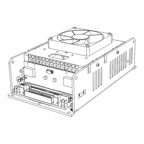
If you find any damage notify the ual and safety instructions. In case you have any questions, shipping company immediately. please do not hesitate to contact your dealer or Powersoft. The DigiMod 3004PFC2 is a four channel amplifier mod- 7 : 3.Disposal of the packing material ules specifically designed to drive high power loudspeakers. -
Page 12: Thermal Constraints
Module and loudspeaker into the same chamber; The thermal resistance of the heatsink derives from the fol- b) Module in a separate vented chamber. Do not obstruct air ow 2 | Digimod 3004 PFC2 | User guide... -
Page 13: Electromagnetic Compatibility (Emc) & Safety
M4 nut and bolt with proper split washer – grover Reject RF noise from input and output cabling by in- washer – to secure the earth terminal lug. stalling ferrite shields. Powersoft suggests the FAIR RITE 0431164181, or equivalent. Electromagnetic Compatibility (EMC) & Safety | 3... -
Page 14: Mechanical Drawings
Warning! The lenght of the thread of the M3 threaded holes is not guaranteed to be the same across the module FIGURE 6: Digimod 3004 PFC2 side and back plate (all dimensions in millimeters). 4 | Digimod 3004 PFC2 | User guide... -
Page 15: Connections
Connections GROUND AC MAINS Faston Faston Faston 6.3 x 0.8 mm 6.3 x 0.8 mm 6.3 x 0.8 mm Channel 1 Channel 2 Faston 6.3 x 0.8 mm Channel 1 Mono Bridge Channel 2 FIGURE 7: DigiMod 3004PFC2 – AC MAINS and audio output wiring: a. -
Page 16: 1.1. Main Connectors Pinout
72-pin SIMM board which would be plugged into the SO5 PL13 Bypass Channel 2 Socket; for more informations about SIMM specifications, reserved Molex 22-27-2031 please contact Powersoft. SIMM board pinout is shown on FIGURE 8. Molex 22-27-2031 Remove jumper to PL22 Molex 22-27-2031... - Page 17 FIGURE 11: DigiMod 3004PFC2 surface components layout. Connections | 7...
-
Page 18: 2.Pl21 Pinout
Active Low, CH1 and CH2 To be pulled to GND by Output Stage Mute MUTE current sink of at least (disable output stages 20 mA PWM) Table continues on the next page... 8 | Digimod 3004 PFC2 | User guide... - Page 19 ...continued from previous page. Scale Imped- Tolle- PIN# Name OUT POWER Range Protected Description factor ance rance Rail Bus Positive +VCCMON +7.5 V 4.5 k� Monitor Rail Bus Negative -VCCMON –7.5 V 4.5 k� Monitor Rail Bus Positive -VCCMON –7.5 V 4.5 k�...
-
Page 20: 3.Pl1000 Pinout
5.4 k� + 47 � Channle 1 BY11 47 � Unbalanced Channle 2 Output BY32 2.7 k� + 47 � Unbalanced Input 112.33 105.30 2.19 106.10 4.04 FIGURE 12: 72-pin SIMM board pinout; dimensions in millimiters. 10 | Digimod 3004 PFC2 | User guide... -
Page 21: 5.Audio Path Block Diagram
10 : 5.Audio path block diagram IN 2 + IN 2 + IN 1 + IN 1 + 47 Ohm 47 Ohm 470p 470p IN 2 – IN 2 – IN 1 – IN 1 – 47 Ohm 47 Ohm 470p 470p BY12... -
Page 22: 6.Protections
±33V, the amplifiers section switch on again. If cooling is not ef- fective, the system may start oscillate. 12 | Digimod 3004 PFC2 | User guide... -
Page 23: 6.7. Harmful Signal Protections
The Main Board and the Control Board microcontrollers high amplitude tend to stress the amplifier section of the work in parallel by triggering fan speed rotation and output module as well as the loudspeakers voice coils. power modulation at different temperature threshold. The When a high frequency stationary loud signals is feed Main Board’s circuitry implements a fan speed control into the amplifier the Control Board limits its mean current... -
Page 24: 7.Led Chart
Main Board secondary protection engaged NORMALLY OFF NORMALLY OFF status Mute ON when MUTE ON ON when MUTE ON protection Main Board primary protection engaged NORMALLY OFF NORMALLY OFF FIGURE 16: Main Board LEDs. 14 | Digimod 3004 PFC2 | User guide... -
Page 25: Evaluation Board - Ktp00477
(mute, CH1-CH2 Bridge Mode energy save enable) in order to evaluate any Powersoft module without using a DSP. When using amp modules CH3-CH4 Bridge Mode that feature on board clip and thermal limiters (such as the... -
Page 26: 2.Test Points
Switched Auxiliary Positive Supply Voltage (switched when engaging energy safe +12SW 1V/V mode) +12VC Auxiliary Positive Supply Voltage (as supplied by module) 1V/V +5VC Auxiliary Positive +5V Supply Voltage (as supplied by module) 1V/V 16 | Digimod 3004 PFC2 | User guide... -
Page 27: 3.Led Description
11 : 3.LED Description Color SIGNAL PRES GREEN Signal presence on input connectors Absence of signal at input connectors Absence of -12V auxiliary voltage. Switched off in 12SW -12VC GREEN Presence of -12V auxiliary voltage case Energy Save status engaged Absence of +12V auxiliary voltage. -
Page 28: 4. Voltage And Thermal Limiter
MUTED 11 : 6.AUX Voltage selector By default most of Powersoft modules provide an auxiliary supply voltage of +/-12V. By activating (ON status) this switch, the module provides an auxiliary volt of +/-15V - not applicable on DigiMod PFC2/4 family. -
Page 29: 8.Energy Save
11 : 8.Energy Save Evaluation board is provided of a signal detection circuit having a wake up threshold of about -59dBV. If Energy save Active, after 10sec of a lack of signal detection, it goes into “shut down / auto mute” state. Depending on the status of ESMODE switch Its behavior may change as follow: If ESMODE ON: (not applicable on DigiMod PFC2/4 family.) When Energy Save Mode is enabled a Shut down of Power Supply of the module (connected to the related output connector). -
Page 30: 10.Block Diagram
11 : 10.Block diagram 20 | Digimod 3004 PFC2 | User guide... -
Page 31: 11.Silkscreen
11 : 11.Silkscreen Evaluation Board - KTP00477 | 21... -
Page 32: 12.Schematic
11 : 12.Schematic PUSH PUSH CH1-2 FEMALE FEMALE BIAS1 BIAS2 DBIAS1 DBIAS2 0603 0603 IN1+ IN2+ IN1- IN2- OUT1 OUT2 BUFIN1 BUFIN2 BUFOUT1 BUFOUT2 BAS28 BAS28 22 | Digimod 3004 PFC2 | User guide... - Page 33 CH3-4 Evaluation Board - KTP00477 | 23...
-
Page 34: 13.Power + Energy Save
11 : 13.Power + Energy Save 24 | Digimod 3004 PFC2 | User guide... -
Page 35: Evaluation Board - Kt000291
12 : 1.Switch functions The KT000291 is a basic evaluation board adapting up to 4 XLR inputs into two Powersoft IDC 34 poles connectors. It includes two switches able to parallel inputs into two paralleled couples. Additional test points help the user to monitor some readout signals and provide some signals to the amplifier. - Page 36 -12VDC 1/2 14,21 Negative Auxiliary Power Supply +VCCMON 1/2 16,19 Positive Rail voltage monitor (20V/V) -VCCMON 1/2 17,18 Negative Rail voltage monitor (20V/V) PL2 Signals on PL1/2 connector (channels 1 and 2) 26 | Digimod 3004 PFC2 | User guide...
- Page 37 Test Point Name type PL3/4 IDC 34 poles pin # Description 5,8,27,30 Secondary ground MUTE 3/4 15,20 Mute channels 3 and 4 (active low) RX232 3/4 reserved TX232 3/4 reserved +5VDC 3/4 +5V (Max absorption 0,1A) 5,8,27,30 Secondary ground IN+3 Positive input channel 3 IN-3 Negative input channel 3...
-
Page 38: Support And Warranty
Powersoft dealer (or to Powersoft for repair. In the latter case, before shipping, distributor). You can also contact the Powersoft Technical you are kindly asked to follow step by step the procedure... -
Page 39: Specifications
Specifications General AC Mains Power Number of channels 4 in / 4 out Universal, regulated switch mode with Power supply PFC (power factor correction) Output power Nominal power requirement AC 100 V - 240 V, 50/60 Hz Maximum output power per channel @ 4 Ω 2000 W Operating voltage AC 90 - 264 V... - Page 40 Page intentionally left blank Support and warranty | 30...
- Page 41 Powersoft S.p.A. Via Enrico Conti, 5 50018 Scandicci (FI) Italy Tel: +39 055 735 0230 Fax: +39 055 735 6235 General inquiries: info@powersoft.it Sales: sales@powersoft.it Application & technical support: support@powersoft.it Service & maintenance: service@powersoft.it Compliance questions: compliance@powersoft.it powersoft-audio.com...
Need help?
Do you have a question about the Digimod 3004 PFC2 and is the answer not in the manual?
Questions and answers