
Subscribe to Our Youtube Channel
Related Manuals for powersoft DSP LITE


Summary of Contents for powersoft DSP LITE
- Page 1 DSP LITE Two-Input Configuration ©2017 Powersoft Keep this manual powersoft_DSPLITE_2inconfig_en_v1.1 for future reference...
- Page 2 Intentionally left blank...
- Page 3 (Figure 3 - Removing the Male XLR) Remove solder from PCB holes with a desoldering pump or a desoldering gun (Fig. 4). (Figure 4 - Removing the solder) Figure 5 portrays the end result. (Figure 5) DSP Lite | 3...
- Page 4 The following step consists of shorting the pads in figure 9. Use the soldering iron with some added solder to ensure proper joining. (Figure 9 - Pads Location) The solder joints should look like in figure 10. (Figure 10 - Shorted Pads) 4 | DSP Lite...
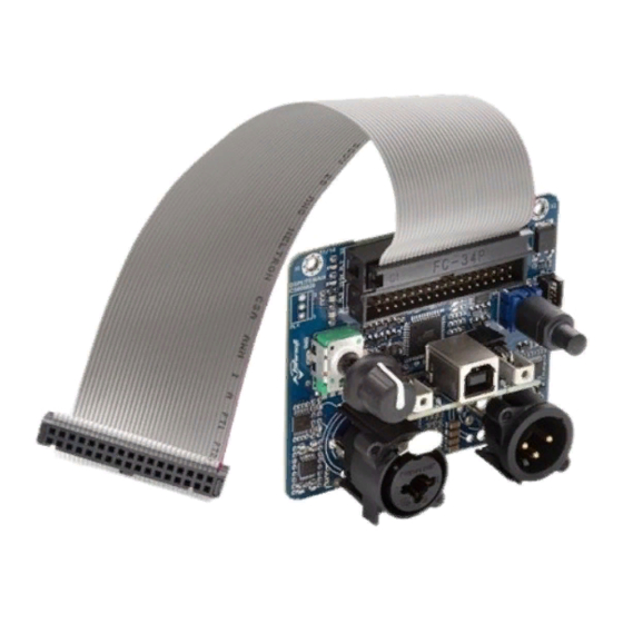
- Page 5 Please refer to the DSP-Lite User Guide for two-input DSP routing configuration. (Figure 11 - Modified DSP Lite) Warning: in order to avoid unwanted short circuits between the conductive parts of the XLR connec- tor, do not use exceeding quantities of solder, as it may seep trough the PCB with unwanted results.
- Page 6 IMPORTANT SAFETY ADDENDUM The aim of this addendum is to describe the safety precautions to be undertaken when servicing any Powersoft amplifier/module. WE RECOMMEND THAT ALL SERVICE OPERATIONS ARE CARRIED OUT BY A TRAINED TECHNICIAN IF NOT EXPLICITLY STATED OTHERWISE, DISCONNECT THE AMPLIFIER FROM THE MAINS.
- Page 7 Intentionally left blank...
- Page 8 Tel: +39 055 735 0230 Fax: +39 055 735 6235 General inquiries: info@powersoft.it Sales: sales@powersoft.it Application & technical support: support@powersoft.it Service & maintenance: service@powersoft.it powersoft-audio.com Data are subject to change without notice. For latest update please refer to the online version available on www.powersoft-audio.com...
Need help?
Do you have a question about the DSP LITE and is the answer not in the manual?
Questions and answers