Table of Contents
Advertisement
Quick Links
Advertisement
Chapters
Table of Contents

Related Manuals for Mindray A8


Summary of Contents for Mindray A8
- Page 1 Operating Instructions Anesthesia System...
- Page 2 Operating Instructions Anesthesia System...
- Page 3 OPTIMIZER® is a registered trademark of Mindray DS USA, Inc. Selectatec® is a registered trademark of Datex-Ohmeda Inc. Copyright © Mindray DS USA, Inc., 2020-2022. All rights reserved. Contents of this publication may not be reproduced in any form without permission of Mindray DS USA, Inc.
-
Page 5: Table Of Contents
Table of Contents Table of Content Safety ..................................1 - 1 Safety Information ........................................1 - 2 Warnings..........................................1 - 2 Cautions ..........................................1 - 7 Notes ............................................1 - 10 Symbols.............................................1 - 11 Product Description............................. 2 - 1 Introduction ............................................2 - 2 Indications For Use......................................2 - 2 Structure and Composition ....................................2 - 2 Functions and Features....................................2 - 2 Equipment Views...........................................2 - 4... - Page 6 Table of Contents Date and Time ........................................4 - 8 Battery Status........................................4 - 9 Fresh Gas Flow Display........................................4 - 10 Electronic Flow Control System ..................................4 - 10 Total Flow Control Mode ..................................4 - 11 Direct Flow Control mode ...................................4 - 12 OPTIMIZER®...
- Page 7 Table of Contents AGSS ............................................4 - 46 Preoperative Tests............................... 5 - 1 Requirements of Preoperative Tests ..................................5 - 2 Preoperative Checklist.........................................5 - 3 Introduction..........................................5 - 3 Suggested Preoperative Checklist ................................5 - 3 Inspect the System........................................5 - 5 System Check..........................................5 - 6 Auto System Check......................................5 - 6 Leak &...
- Page 8 Table of Contents Set Anesthetic Agent ......................................6 - 4 Select the Desired Anesthetic Agent ...............................6 - 5 Adjust the Concentration of Anesthetic Agent ...........................6 - 5 Set Ventilation ..........................................6 - 5 Change Ventilation Mode ....................................6 - 5 Set Manual Ventilation Mode..................................6 - 6 Settings Before Starting the Automatic Ventilation Mode........................6 - 7 Volume Control Ventilation (VCV) ................................6 - 7 Set Pressure Control Ventilation (PCV) ...............................6 - 8...
- Page 9 Table of Contents Types of Alarms and Messages..................................8 - 2 Alarm Indicators........................................8 - 2 Alarm Display..........................................8 - 4 Display Rules of Alarm Messages..................................8 - 5 Setting Alarm Volume .........................................8 - 6 Pause Alarm Audio........................................8 - 7 Alarm Reset............................................8 - 7 Setting Alarm Limits ........................................8 - 8 Auto Alarm Limits.......................................8 - 10 View Active Alarms ........................................8 - 11...
- Page 10 Table of Contents Periodic Maintenance ........................................9 - 29 Product Specifications............................10 - 1 Standards Compliance ......................................10 - 2 Safety Designations........................................10 - 4 Physical Specifications......................................10 - 4 Environmental Specifications ....................................10 - 6 Electrical Specifications......................................10 - 6 Main Electrical Power Specifications ................................
- Page 11 Table of Contents History ...............................................B - 6 Lung Recruitment .........................................B - 6 Fresh Gas Control ..........................................B - 6 Patient Information ........................................B - 7 Ventilation Mode...........................................B - 7 Ventilation Linkage Parameters ....................................B - 10 Constraints Among Ventilation Parameters................................B - 14 Operating Principles............................C - 1 Pneumatic Diagram........................................C - 2 Electric System Structure......................................C - 6 Abbreviations, Symbols, and Units of Measure ....................D - 1...
- Page 12 Table of Contents This page intentionally left blank. Anesthesia System Operator’ s Manual viii...
- Page 13 Mindray or repairs by people other than Mindray authorized personnel.
- Page 14 Anesthesia System which are designated as repairable. Manufacturer and Address Manufacturer: Shenzhen Mindray Bio-Medical Electronics Co., Ltd. Address: Mindray Building, Keji 12th Road South, High-tech industrial park, Nanshan, Shenzhen 518057, P.R. China Anesthesia System Operator’ s Manual...
- Page 15 A8 Anesthesia System (herein referred to as Anesthesia System, Operator’s Manual Equipment, A8) contains the instructions necessary to operate the product safely and in accordance with its function and intended use. Observance of this manual is a prerequisite for proper product performance and correct operation and ensures patient and operator safety.
- Page 16 Responsibilities of Operators This page intentionally left blank. Anesthesia System Operator’ s Manual...
-
Page 17: Safety
Safety Safety Information....................................1-2 Symbols ........................................1-11 1 - 1 Operator’s Manual of Anesthesia System... -
Page 18: Safety Information
WARNING: Do not open the equipment housings. All servicing and future upgrades must be carried out only by trained and authorized Mindray personnel. WARNING: Do not rely exclusively on the audible alarm system for patient monitoring. - Page 19 Safety Safety Information WARNING: The physiological parameters and alarm messages displayed on the screen of the equipment are for the caregiver’s reference only and cannot be directly used as the basis for clinical treatment. WARNING: Dispose the packaging material, observing the applicable waste control regulations and keeping it out of children's reach.
- Page 20 Safety Information Safety • Refer to the material safety data sheet as applicable. • Refer to the operation and maintenance manuals of all disinfection equipment. • Do not inhale fumes produced during any disinfection process. WARNING: Use extreme care while handling the CO absorbent as it is a caustic irritant.
- Page 21 Therefore, oil and grease should not be used where oxygen enrichment may occur. WARNING: Use of lubricants not recommended by Mindray may increase the danger of fire or explosion. Please use lubricants as approved by Mindray. WARNING:...
- Page 22 WARNING: If the Drive Gas Pressure Low alarm occurs when the gas supply pressure is greater than 200 kPa, contact your service personnel or Mindray. WARNING: Make sure that CO can be fully absorbed by the absorbent after the absorbent is replaced or a CO absorbent canister is installed.
-
Page 23: Cautions
Safety Safety Information WARNING: The anesthesia system may lose its balance if it is tilted more than 10 degrees. Use extreme caution when moving or resting the equipment on slopes of over 10 degrees. Before moving, remove all equipment from the top shelf, all monitoring equipment mounted to the side of this machine, all brackets, cylinders, objects on the top self and worktable and in the drawers. - Page 24 Do not connect any non-isolated devices to the DB9/RS232C interface of the equipment. CAUTION: Do not connect any devices to the SB ports other than Mindray approved USB storage devices and a supported USB mouse. CAUTION: Do not wash the inner surface of the oxygen sensor.
- Page 25 (MRI) environment. CAUTION: To ensure measurement accuracy and to avoid possible damage to the equipment, use only Mindray-approved cables and accessories. CAUTION: Use the power cord provided with the product. If a substitute is necessary, use power cord in compliance with the specification.
-
Page 26: Notes
Safety Information Safety CAUTION: Turn the flow control knob of the backup flow control system slowly. To avoid damaging the control valves, do not turn further when the flowmeter reading is out of range. When turning a flow control knob clockwise to decrease flow, the flowmeter should reach 1 L/min before the knob reaches its most clockwise mechanical stop (off) position. -
Page 27: Symbols
Safety Symbols NOTE: The system is designed to be equipped with an anesthetic vapor delivery device that complies with ISO 80601-2-13. NOTE: The battery supply of this equipment is not a user serviceable component. Only an authorized service representative can replace the battery supply. If the system is not used for a long time, contact a service representative to have the battery supply disconnected. - Page 28 Symbols Safety SYMBOL DESCRIPTION SYMBOL DESCRIPTION Caution! Warnings Temperature limitation Humidity limitation Atmospheric pressure Keep dry limitation Fragile, handle with This way up care Stacking limit by Recyclable number Ambient: temperature Ambient: humidity range range Electrical: alternating Electrical: internal current (AC) battery Electrical: Electrical: protective...
- Page 29 Safety Symbols Material: polyethylene Material: polysulfone sulfone (PPSU) Assemble volume Disassemble O sensor exchanger Sensor Connector Gas: O flush button Lock/Unlock: locked Lock/Unlock: unlocked Manual ventilation Automatic ventilation Water Drain Watertrap No heavy objects: Do Not Oil Do Not Crush Autoclavable Not Autoclavable 134°C...
- Page 30 Symbols Safety Identifier: manufacturer’s Identifier: serial reference/catalog number number Protection level of Applied parts of IPX1 anesthesia system defibrillator proof type against splashing water BF equipment Refer to instruction Identifier: Manufacturer manual/booklet MR Unsafe - keep away from magnetic resonance imaging (MRI) equipment Conforms to AAMI Std.
- Page 31 Safety Symbols Battery level is low and it is powering the system. Recharging Medium priority message recommended. AC power is not connected. Battery is not installed High priority message Operator’ s Manual of Anesthesia System 1 - 15...
- Page 32 Symbols Safety This page intentionally left blank. 1 - 16 Operator’ s Manual of Anesthesia System...
-
Page 33: Product Description
Product Description Introduction .........................................2-2 Equipment Views......................................2-4 Operator’ s Manual of Anesthesia System 2 - 1... -
Page 34: Introduction
Introduction Product Description Introduction 2.1.1 Indications For Use The Anesthesia System is a device used to administer to a patient, continuously or intermittently, a general inhalation anesthetic and to maintain a patient's ventilation. The Anesthesia System is intended for use by licensed clinicians in the administration of general anesthesia, for patients requiring anesthesia within a health care facility, and can be used in adult, pediatric and neonate populations. - Page 35 Product Description Introduction • Cardiopulmonary bypass • Monitor mode • Lung Recruitment (optional) • High-flow Nasal Cannula Oxygen (HFNC) • Flow pause • Anesthetic breathing system purge • Agent usage calculation • Anesthetic gas monitoring (with paramagnetic O sensor) • Oxygen concentration monitoring •...
-
Page 36: Equipment Views
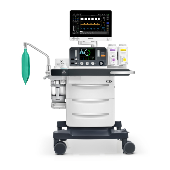
Equipment Views Product Description Equipment Views 2.2.1 Main Unit (Front View) Figure 2-1 Main Unit (Front View) PARTS DESCRIPTION The alarm LED may turn red, yellow or cyan, indicating Alarm LED different priorities. Red = high priority, yellow = medium priority, cyan = low priority, off = no alarms. - Page 37 Product Description Equipment Views PARTS DESCRIPTION High-flow Nasal Cannula There is a float in the flow tube, and the scale line that the middle of the float is aligned to indicates the current gas flow. Oxygen (HFNC) There is a flow control knob on the flowmeter to control the flow.
- Page 38 Equipment Views Product Description PARTS DESCRIPTION AC status indicator The indicator is on when the system is connected to an AC power source. Used to switch on or off the system. System switch Key lock The key and lock to lock a drawer. Gas supply pressure gauge Used to indicate the pressure of the O , air and N...
-
Page 39: Main Unit (Rear View)
Product Description Equipment Views 2.2.2 Main Unit (Rear View) Figure 2-2 Main Unit (Rear View) PARTS DESCRIPTION Used to install the display. Display arm Breaker The breaker for each auxiliary output power outlet. Auxiliary AC power outlet Four auxiliary AC power outlets are available. Hanger Used to hang cables and gas supply hoses. - Page 40 SB interfaces (SB1, SB2, SB3, SB4) CAUTION: Do not connect any devices to the SB ports other than Mindray approved USB storage devices and a supported USB mouse. Equipotentiality Used to provide a grounding point. Used to eliminate the electric potential difference between the ground wires of different devices to ensure safety.
-
Page 41: Main Unit (Left View)
Product Description Equipment Views 2.2.3 Main Unit (Left View) Figure 2-3 Main Unit (Left View) Operator’ s Manual of Anesthesia System 2 - 9... - Page 42 Equipment Views Product Description PARTS DESCRIPTION Used to install the standard attachment arms of the monitor and Installing rail other equipment. Installing rails are available on both sides of the equipment. High-flow Nasal Used to output O when the High-flow Nasal Cannula Oxygen (HFNC) feature is enabled.
-
Page 43: Main Unit (Right View)
Product Description Equipment Views 2.2.4 Main Unit (Right View) Figure 2-4 Main Unit (Right View) PARTS DESCRIPTION Work lamp switch Used to turn on/off the work lamp. Three settings are available: off, low-light and high-light. Users can only turn on the work lamp when the system is switched on. Work lamp Located beneath the display to illuminate the worktable. -
Page 44: Main Unit (Top View)
It is normal to have a minor difference between the airway pressure gauge reading and the electronically monitored value. When the difference is greater than 15%, please contact your service personnel or Mindray. Used to switch between the automatic ventilation and Manual/Auto switch manual ventilation modes. Handle... -
Page 45: Breathing System
Product Description Equipment Views PARTS DESCRIPTION APL valve Used to set the rotary pressure regulating valve of the breathing system during manual ventilation. Its scales represent the approximate pressure values. Set the APL valve to the SP position during spontaneous respiration. Elevate the APL valve upward as needed to release the pressure quickly. -
Page 46: Negative Pressure Suction Device
Equipment Views Product Description PARTS DESCRIPTION Expiration connector The expiration connector of the breathing circuit. The inspiration connector of the breathing circuit. Inspiration connector Used to connect to a manual ventilation bag. Bag arm Used to install the O sensor to monitor the O concentration. -
Page 47: Installation And Disassembly
Installation and Disassembly Unpacking........................................3-3 Initial Setup........................................3-3 Breathing System......................................3-3 Vaporizer ........................................3-4 Negative Pressure Suction Device ..............................3-5 High-flow Nasal Cannula Oxygen (HFNC) Tube........................3-7 Anesthetic Gas Scavenging System (AGSS) ..........................3-8 Connect Anesthesia System with Information System....................3-11 Connect Anesthesia System to Patient Monitor ........................ 3-12 Connect Anesthesia System with eGateway........................ - Page 48 Installation and Disassembly WARNING: Before installation, check the adequacy of the surface of the structure to which the equipment is to be attached. WARNING: This equipment must be installed by a factory authorized representative. WARNING: Continuous use of desiccated soda lime may endanger patient safety. Adequate precautions should be taken to ensure that the soda lime in the CO absorbent canister does not become desiccated.
-
Page 49: Unpacking
Save all damaged factory packaging until further instructed by Mindray. The receiver should immediately contact Mindray Customer Service. Initial Setup The initial setup of the anesthesia system must be performed by an authorized Mindray service representative. Please contact Mindray Technical Support for any additional assistance. Breathing System Please install the breathing system, refer to 9.7.3.4 "Reassembly". -
Page 50: Vaporizer
Vaporizer Installation and Disassembly Vaporizer The equipment contains a 2-position vaporizer system to enable anesthetic agents to be introduced into the fresh gas flow. Two vaporizers are supported, but only one vaporizer can be used at a time. Isoflurane, Desflurane and Sevoflurane vaporizers can be used. ®... -
Page 51: Filling And Draining The Vaporizer
Installation and Disassembly Negative Pressure Suction Device Locking Mechanism Handle in the Locked Position Figure 3-2 Vaporizer, locked Finally, check the following items: a. Ensure that the top of the vaporizer is horizontal. If not, remove and reinstall the vaporizer. b. -
Page 52: Turn On Negative Pressure Suction Device
Negative Pressure Suction Device Installation and Disassembly Insert the suction tube to the overfill protection connector. The negative pressure suction device is now fully installed. Overfill protection connector Filter Suction tube Liquid collection bottle Figure 3-3 Install the negative pressure suction device NOTE: When installing the filter to the suction tube, pay attention to keeping the side printed with IN facing the liquid collection bottle. -
Page 53: High-Flow Nasal Cannula Oxygen (Hfnc) Tube
Installation and Disassembly High-flow Nasal Cannula Oxygen (HFNC) Tube High-flow Nasal Cannula Oxygen (HFNC) Tube Hang the humidifier on the bracket on the side of the anesthesia system. Bracket Humidifier Figure 3-4 Install the humidifier Connect the gas inlet of the humidifier and the HFNC outlet of the anesthesia system with a breathing tube. -
Page 54: Anesthetic Gas Scavenging System (Agss)
Anesthetic Gas Scavenging System (AGSS) Installation and Disassembly Anesthetic Gas Scavenging System (AGSS) 3.7.1 Active AGSS • When the ACGO circuit needs to scavenge the gas to the AGSS, connect the AGSS port with the ACGO as shown below. Connecting to the ACGO circuit Figure 3-6 Active AGSS (connecting to the ACGO circuit) •... -
Page 55: Passive Agss
Installation and Disassembly Anesthetic Gas Scavenging System (AGSS) • When both the patient monitor and ACGO circuit need to scavenge the gas to the AGSS, use the adapter as shown below. Connecting to the patient monitor via sampling tube Connecting to the ACGO circuit Figure 3-8 Active AGSS (connecting to the patient monitor and ACGO circuit) 3.7.2 Passive AGSS... - Page 56 Anesthetic Gas Scavenging System (AGSS) Installation and Disassembly • When the gas path of the patient monitor does not meet the biological compatibility standard, the patient monitor needs to scavenge the waste gas to the AGSS. Use the adapter as shown below.
-
Page 57: Connect Anesthesia System With Information System
Installation and Disassembly Connect Anesthesia System with Information System Connect Anesthesia System with Information System 3.8.1 Connect Anesthesia System with Information System Through Serial Interface The anesthesia system can be connected to the information system through a serial interface and send its ventilation modes, status, parameters, alarms, alarm limits and patient information to the information system by the HL7 protocol. -
Page 58: Connect Anesthesia System To Patient Monitor
Connect Anesthesia System to Patient Monitor Through Serial Interface The anesthesia system can be connected to a Mindray patient monitor through a serial interface and the BeneLink module to send the ventilation modes, parameters, alarms, alarm limits, waveforms and patient information to the patient monitor via the MR-WATO protocol. - Page 59 System Interface Main Screen........................................4-2 System Information Title ..................................4-3 Fresh Gas Flow Display..................................4-10 Waveform/Parameter/Spirometry/Trend Display Zone....................4-15 Ventilation Mode Tabs..................................4-22 System Soft Key....................................... 4-22 Setup Menu....................................... 4-27 Status Screen......................................4-45 Operator’ s Manual of Anesthesia System 4 - 1...
-
Page 60: System Interface
Main Screen System Interface Main Screen Figure 4-1 Main Screen SERIAL MAIN SCREEN DESCRIPTION Patient information Shows the information of the current patient, including the patient type, weight and age. You can click on the section to view more personal information of the patient. See (Pages 4-3) 4.2.1 "Patient Information". -
Page 61: System Information Title
System Interface System Information Title SERIAL MAIN SCREEN DESCRIPTION Alarm/prompt message zone Displays physiological alarms, technical alarms and prompt messages. The most recent and top-priority alarm is displayed in the topmost section. Other alarms are displayed in the lower section, grouped by priority for scrolled display. - Page 62 System Information Title System Interface Figure 4-2 Patient information icon Figure 4-3 Patient Information menu NOTE: The equipment saves the latest patient parameter settings for each patient type: Adult, Pediatric, and Neonate. Changing to another patient size does not clear the parameter settings for the previous patient size. For example, changing from Adult to Pediatric and back to Adult will result in the Adult patient parameter settings still being saved.
-
Page 63: Set Patient Information In Anesthesia System
System Interface System Information Title EDITABLE FIELD DESCRIPTION Room Enter up to 30 digits for each field. Department Facility Table 4-2 Patient information 4.2.1.1 Set Patient Information in Anesthesia System NOTE: The patient type can be changed only when the equipment is in the standby or manual mode. -
Page 64: Timer (Elapsed Timer/Countdown Timer)
System Information Title System Interface Set the network and ensure that the network access is normal. a. Enter Standby mode. b. Select the icon to open the [Setup] menu. c. Select the [System] soft key, enter the system password and confirm the password. d. -
Page 65: Alarm And Prompt Message
System Interface System Information Title 4.2.3 Alarm and Prompt Message Displays physiological alarms, technical alarms and prompt messages. The most recent and top- priority alarm is displayed in the topmost section. Other alarms are displayed in the lower section, grouped by priority. In each group, the most recent alarm is displayed on the top of the list. Select the zone to display a list of all active alarms. -
Page 66: Screen Brightness
System Information Title System Interface 4.2.5 Screen Brightness Select the screen brightness adjustment icon to adjust the brightness of the Main Screen or Status Screen on the pop-up screen. indicates the lowest brightness and indicates the highest brightness. Figure 4-8 Screen brightness adjustment icon 4.2.6 Volume Select the volume adjustment icon to adjust the alarm volume, the system alert volume, the key click... -
Page 67: Battery Status
System Interface System Information Title Enter Standby mode. Select the icon to open the [Setup] menu. Select the [System] soft key, enter the system password and confirm the password. Select the [Setup] tab in the system menu. Select the [Time/Date] tab. Adjust [24 Hour Time], [Time Zone], [Date], [Time], [Date Format] and [Daylight Savings Time] in the pop-up menu. -
Page 68: Fresh Gas Flow Display
Fresh Gas Flow Display System Interface The battery icon on the screen indicates the status of the battery. PARTS DESCRIPTION Battery is fully charged. AC power supply is connected. Equipment is powered by the AC power supply. The solid part of the battery icon represents the remaining battery level. -
Page 69: Total Flow Control Mode
System Interface Fresh Gas Flow Display 4.3.1.1 Total Flow Control Mode The total flow control mode of the EFCS is shown in the figure below: Displays the flow of the balance gas The OPTIMIZER® indicator, is used to indicate the relationships between the settings and the optimizers. -
Page 70: Direct Flow Control Mode
Fresh Gas Flow Display System Interface • Set the [Balance Gas] to [Air], [N O] or [None]. • Set the total flow. • Set the O concentration value. 4.3.1.2 Direct Flow Control mode The direct flow control mode of the EFCS is shown in the figure below: Displays the flow of the balance gas The OPTIMIZER®... -
Page 71: Optimizer
System Interface Fresh Gas Flow Display You can perform the following settings in the Direct Flow Control menu: • Set 100% O flow rate using quick keys. • Set the [Control Mode] to [Total Flow] or [Direct Flow]. • Set the [Balance Gas] to [Air], [N O] or [None]. - Page 72 Fresh Gas Flow Display System Interface If the anesthesia system is connected with the monitor, the anesthesia system can have access to the AG or CO data from the monitor (Passport 12M / 17M). Perform the following operations: The network cable is connected to the ethernet interface of the anesthesia system on one end and connected to the ethernet interface of the monitor on the other end.
-
Page 73: Backup Flow Control System
System Interface Waveform/Parameter/Spirometry/Trend Display Zone 4.3.2 Backup Flow Control System If the EFCS fails, the system automatically opens the Backup Flow Control System (hereinafter referred to as the BFCS) cover, and adjusts the gas flow with the needle valve of flowmeter. Before the EFCS is restored, you cannot disable the BFCS. - Page 74 Waveform/Parameter/Spirometry/Trend Display Zone System Interface Select this control to set the desired Select this control to set the desired waveforms, parameters, spirometry spirometry screen to display. and trends to display. Scroll bar. Generally, Select the control to expand or scrolling the bar will collapse the zone on the right.
-
Page 75: Waveform/Parameter Screen
System Interface Waveform/Parameter/Spirometry/Trend Display Zone 4.4.1 Waveform/Parameter Screen Displays the pressure, flow rate, volume, CO O, and AA waveforms and monitoring parameters. Select this control to select the desired waveforms and monitoring parameters to display on the pop-up screen. Waveform and its monitoring parameters Monitored parameters Figure 4-19 Waveform/parameter screen 4.4.2... -
Page 76: Loop Type
Waveform/Parameter/Spirometry/Trend Display Zone System Interface Spirometry Figure 4-20 Spirometry 4.4.2.1 Loop Type The [Loop Type] option is used to display the P-V, the F-V, or the P-F loop on the spirometry screen. Loop Type Show Reference Save Loop Review Loops Figure 4-21 Soft keys of loops: Loop Type, Show Reference, Save Loop and Review Loops 4.4.2.2 Show Reference... -
Page 77: Save Loop
System Interface Waveform/Parameter/Spirometry/Trend Display Zone 4.4.2.3 Save Loop Select the [Save Loop] soft key to save the current loop (including its monitoring parameter data) as a baseline loop or reference loop. You can save a maximum of one baseline loop and four reference loops. -
Page 78: Mini Trends Screen
Waveform/Parameter/Spirometry/Trend Display Zone System Interface Selected loops (small) Selected reference loops (large) Unselected loops Digital data zone Delete a loop Loop Type Figure 4-22 Review Loops window Parameter data zone: Displays the monitoring parameter data related to the saved baseline loop and reference loops. -
Page 79: Compl/Peep Trend Screen
System Interface Waveform/Parameter/Spirometry/Trend Display Zone Select this control to enable or disable the mini trends waveform on the pop-up screen. Mini Trends Figure 4-23 Mini Trends 4.4.4 Compl/PEEP Trend Screen Compl and PEEP trend waveforms are displayed at the same time on the pop-up screen. The Compl/ PEEP Trend duration can be set as follows: Select the icon >... -
Page 80: Ventilation Mode Tabs
Ventilation Mode Tabs System Interface Ventilation Mode Tabs Displays tabs for ventilation modes. Each tab displays the ventilation mode and its parameters. The ventilation modes on the screen can be customized. Select ventilation mode custom soft key to open [Vent Mode Setup] menu. In the opened menu, set the ventilation modes to be displayed in ventilation mode zone. -
Page 81: History
System Interface System Soft Key 4.6.1 History Select the [History] soft key on the Main Screen to open the [History] menu. The menu contains the List Trends, the Graphic Trends, the Event Log, Screen and Export tabs. The List Trends, Graphic Trends and Event Log tabs on the History screen are associated. -
Page 82: Graphic Trends
System Soft Key System Interface BUTTON FUNCTION Next Event The cursor moves from the current event to the next event. Table 4-4 List Trend Events Buttons 4.6.1.1.3 Display Interval In the List Trends menu, you can set the display interval to [1 Min], [5 Min], [10 Min], [15 Min], [30 Min], [1 Hour] and [2 Hour]. -
Page 83: Event Log
System Interface System Soft Key BUTTON FUNCTION Previous Event The cursor moves from the current event to the previous event. Next Event The cursor moves from the current event to the next event. Table 4-5 Graphic Trend Events Buttons 4.6.1.2.3 Zooming In the Graphic Trends menu, you can set the zooming to [1 Min], [5 Min], [10 Min], [15 Min], [30 Min], [1 Hour] and [2 Hour]. -
Page 84: Export
System Soft Key System Interface 4.6.1.5 Export Insert a U disk to the USB interface of the equipment as per the prompts on the screen. Select the [Export] soft key to export list trends, graphic trends, event logs and captured screens to the U disk. The exported data is in the format of .html. -
Page 85: Cardiac Bypass Mode
NOTE: The [System] soft key is only available in the standby mode. NOTE: The [Service] tab is for use only by Mindray Technical Service. Please contact Mindray Technical Support for details. Operator’ s Manual of Anesthesia System 4 - 27... -
Page 86: Ventilation
Setup Menu System Interface 4.7.1 Ventilation Figure 4-31 Ventilation (taking AG module configuration for example) Vt/IBW The system calculates the default tidal volume in the ventilation mode based on the [Vt/IBW] value. It is available for the VCV, SIMV-VC, PCV-VG, and SIMV-VG modes. Vt Source Set the [Vt Source] to [IBW] or [Patient Type]. - Page 87 System Interface Setup Menu Plimit Line Set the [Plimit Line] to (off ) or (on). The Plimit line function displays a dashed line in the Pressure waveform area to indicate the Plimit position. The Plimit line can be displayed in VCV, SIMV-VC, SIMV-VG and PCV-VG modes.
-
Page 88: Oxygen (O2)
Setup Menu System Interface 4.7.2 Oxygen (O Figure 4-32 Oxygen (O Calibrate O Sensor You can select the [Calibrate O Sensor] button to calibrate the O sensor. Follow the prompts on the screen to perform the operation: See "21% Oxygen Calibration" on Pages 9-4 for more information. - Page 89 System Interface Setup Menu Figure 4-33 Information Operator’ s Manual of Anesthesia System 4 - 31...
-
Page 90: Screen
When the system enters the screen saver status, the status screen is displayed as blank, and the Main Screen displays Mindray at random locations as the screen saver. The system will exit from the screen saver when it detects the following operations: •... -
Page 91: Export System Data
System Interface Setup Menu Clean Screen When the [Clean] soft key is selected, the system will lock the screen for 10 seconds so that the display can be cleaned. 4.7.6 Export System Data Figure 4-35 Export System Data The anesthesia system can export system data. The system data includes the equipment information, logs, monitoring data, system information, historical data, captured screens and network information. -
Page 92: Calibrate
Setup Menu System Interface 4.7.7 Calibrate Figure 4-36 Calibrate Follow the prompts on the screen to calibrate the flow sensor. See (Pages 9-4) 9.3 "Flow Sensor Calibration" for more information. 4.7.8 System The [System] menu is accessible only by authorized administrative service personnel with password access. - Page 93 System Interface Setup Menu Figure 4-37 Setup > System > Calibrate menu MENU DESCRIPTION Select [Begin] to calibrate the O sensor and follow the prompts on the screen. sensor See (Pages 9-4) 9.4 "O Sensor Calibration". Select [Begin] to zero the flowmeter and follow the prompts on the screen. Zero Flow Meters NOTE: Before zeroing the flowmeter, make sure that the gas...
-
Page 94: Setup
Setup Menu System Interface 4.7.8.2 Setup Figure 4-38 Setup > System > Setup menu MENU OPTION DESCRIPTION When [Insp Pressure] is set to [Pinsp], the inspiration pressure parameter in the PCV and SIMV- PCV ventilation modes is [Pinsp]. When [Insp Ventilation Insp Pressure Pressure] is set to [ΔPinsp], the inspiration pressure... - Page 95 System Interface Setup Menu MENU OPTION DESCRIPTION When the [Alarm Reset] is enabled, the Main Screen will display the [Alarm Reset] soft key. When the Alarm Reset [Alarm Reset] is disabled, the Main Screen will not display the [Alarm Reset] soft key. When the [Capture Event/Screen] is enabled, the Main Screen will display the [Capture Event/ Screen] soft key.
- Page 96 Setup Menu System Interface MENU OPTION DESCRIPTION 24 Hour Time Enables or disables the 24 Hour Time. Selects to set the UTC time zone. Time Zone Sets the current time. Time Sets the date format. Date Format Date Sets the current date. The [Daylight Savings] can be set to [Auto], [On] or [Off ].
-
Page 97: Profiles
System Interface Setup Menu 4.7.8.3 Profiles Figure 4-39 Setup > System > Profiles menu Operator’ s Manual of Anesthesia System 4 - 39... - Page 98 Setup Menu System Interface MENU OPTION DESCRIPTION Delete 10 factory profiles are displayed by default. In practical application, the operator may make some changes to some settings and these changes can Rename be saved as user profiles. The anesthesia system saves the profiles in real time and the saved profiles are called recent profiles.
-
Page 99: Network
System Interface Setup Menu 4.7.8.4 Network Figure 4-40 Setup > System > Network menu Operator’ s Manual of Anesthesia System 4 - 41... - Page 100 Sets the serial communication protocol. NOTE: If the protocol is set to MR- WATO, the anesthesia system Protocol supports communications with a Mindray patient monitor with the Mindray Benelink module. Baud Rate Sets the Baud rate. Data Bits Sets the data bits.
- Page 101 System Interface Setup Menu MENU OPTION DESCRIPTION Destination IP Sets the destination IP address. Sets the port. Port Select the [Test] soft key, and the system will start Test Results the network test and display the test results. Data+ Data Internal Sets the data intervals.
-
Page 102: Information
Displays the equipment ID, MAC address and system features status. Figure 4-41 Setup > System> Information menu 4.7.9 Service Tab Accessible only by Mindray-authorized service personnel. Please contact Mindray Technical Support for assistance. 4 - 44 Operator’ s Manual of Anesthesia System... -
Page 103: Status Screen
System Interface Status Screen Status Screen 4.8.1 Volume Exchanger The Status Screen does not display the volume exchanger when in standby, ACGO and Monitor modes. 4.8.1.1 Automatic Ventilation, Flow Pause or Bypass The system provides a VTi loop and dynamic lung to indicate the operation status of the volume exchanger during ventilation. -
Page 104: Agss
Status Screen System Interface Gas Supply Pressure Figure 4-44 Gas Supply Pressure Monitoring To change the gas supply pressure unit, perform the following settings: Select the soft key > [System] soft key (system password required) > [Setup] > [Language/Unit] tab. Set [Gas Supply Pressure] to [kPa], [psi] or [bar]. -
Page 105: Preoperative Tests
Preoperative Tests Requirements of Preoperative Tests.............................5-2 Preoperative Checklist ...................................5-3 Inspect the System ....................................5-5 System Check......................................5-6 Power Failure Alarm Test ..................................5-7 Pipeline Test.........................................5-7 Basic Ventilation Test....................................5-8 Backup Gas Cylinder Test..................................5-9 Flow Control System Test................................. 5-10 Vaporizer Test......................................5-12 Breathing System Test ..................................5-13 Alarm Test........................................ -
Page 106: Requirements Of Preoperative Tests
NOTE: Do not use the anesthesia system if a test failure occurs. Please contact Mindray Technical Support for any additional assistance. NOTE: Provide a checklist of the anesthetic system, including anesthetic gas delivery system, monitoring device, alarm system, and protective device, which are intended to be used for the anesthetic system, whether they are used alone or assembled together. -
Page 107: Preoperative Checklist
Preoperative Tests Preoperative Checklist Preoperative Checklist 5.2.1 Introduction The purpose of preoperative check is to detect potential system problems before use. An effective method for detecting pneumatic circuit occlusions, leaks, and other system problems can be found in the procedures of preoperative checks. In addition, it is recommended that the breathing circuit be tested for the ability to effectively deliver positive pressure ventilation before each ventilation begins. - Page 108 Preoperative Checklist Preoperative Tests Prior to administering anesthesia to each patient, the following should be done: Check for any damage to or dangerous conditions in the equipment. Ensure all necessary equipment and supplies are present, e.g., drugs, CO absorbent (not exhausted), breathing circuits and backup O supply.
-
Page 109: Inspect The System
Preoperative Tests Inspect the System Inspect the System NOTE: Ensure that the breathing system is correctly connected and not damaged. Perform the following inspections before operating the equipment: The equipment is correctly connected and it is in good condition. Inspect the system for: a. -
Page 110: System Check
Preoperative Check Displays the checks to be performed before Mindray. List operating the system. Table 5-1 System Check NOTE: Select the [Alarms] soft key > [Limits] tab on the Main Screen. Set the... -
Page 111: Leak & Compliance Test
Preoperative Tests Power Failure Alarm Test 5.4.2 Leak & Compliance Test NOTE: The system records the result of the last Automatic Circuit Leak Test on its standby screen, indicating whether the test was passed, failed, or skipped. From system being turned on: When the system is turned on, it automatically initiates the Power On Self Test (POST). -
Page 112: Air Pipeline Test
Basic Ventilation Test Preoperative Tests NOTE: Different from O pipeline supply, when N O supply is disconnected, the anesthesia system with no pressure sensor configured will issue no alarms related to N O pressure as N O pressure decreases. Connect O and N O pipeline supplies. -
Page 113: Backup Gas Cylinder Test
Preoperative Tests Backup Gas Cylinder Test Set the ventilator controls according to the following table: VENTILATOR CONTROLS VENTILATOR SETTINGS Patient Size Adult Ventilation Modes Target Pressure - Pinsp Respiratory Rate - RR I:E Ratio - I:E PEEP - PEEP Inspiratory Rise Time - Tslope Select PCV and begin ventilation. -
Page 114: High Pressure Leak Test Of Air Cylinders
Flow Control System Test Preoperative Tests Record the current pressure of the cylinder. Close the valve of the N O cylinder. Record the cylinder pressure after one minute. If the pressure reduction of the backup gas cylinder exceeds 0.5 MPa (72.5 psi), install a new cylinder gasket. - Page 115 Preoperative Tests Flow Control System Test Adjust the Air flow. Make sure that the displayed reading of electronic flowmeter is consistent with the setting. Set [Balance Gas] to [N Adjust the N O flow gradually. Make sure that the O flow increases with the increase of N flow and that the O and N...
-
Page 116: Vaporizer Test
Vaporizer Test Preoperative Tests 5.10 Vaporizer Test WARNING: During the vaporizer test, the anesthetic agent comes from the fresh gas outlet. Use a safe and approved procedure to remove and collect the agent. Before the test, ensure that the vaporizers are correctly installed. For detailed steps, see "Vaporizer" on Pages 3-4. -
Page 117: Breathing System Test
Preoperative Tests Breathing System Test Set the APL valve to the 70 cmH O position. Push the [O Flush] button until the airway pressure gauge value is about 30 cmH 10. Release the [O Flush] button. Make sure that there is no pressure decrease on the airway pressure gauge. -
Page 118: Alarm Test
Alarm Test Preoperative Tests 5.12 Alarm Test Alarms also can be verified by creating an alarm condition on the equipment and verifying the corresponding alarm indicators are present on the anesthesia system. 5.12.1 Prepare for Alarm Tests Connect the test lung or manual bag to the Y-piece of the breathing circuit. Set the Auto/Manual switch to the Auto position. -
Page 119: Minute Volume (Mv) Too Low Alarm Test
Preoperative Tests Alarm Test Set the FiO low alarm limit back to a value lower than the measured O value and make sure that the alarm cancels. Install the O sensor back to the breathing system. Select the Alarms soft key and then the Limits tab. Set the FiO high alarm limit to 50%. -
Page 120: Continuous Airway Pressure Too High Alarm Test
Alarm Test Preoperative Tests 5.12.5 Continuous Airway Pressure Too High Alarm Test Connect the manual bag to the manual bag port. Set the O flow to the minimum value. Turn the APL valve control to set the APL valve to 30 cmH O position. -
Page 121: Inspect The Agss
Preoperative Tests Inspect the AGSS Ensure that the [EtAA Too Low] alarm appears on the screen. 5.13 Inspect the AGSS Connect to the O supply. Connect the waste gas outlet of the anesthesia system to the EVAC port or the vacuum port of healthcare facility and turn on the waste gas disposal system. - Page 122 Pre-operation Preparations Preoperative Tests Ensure that the breathing system is correctly connected and not damaged. WARNING: Before connecting the equipment to the patient, flush the device with at a flow of 8 L/min for at least two minutes. This removes unwanted mixtures and by-products from the system.
-
Page 123: Operations
Operations Powering On the Anesthesia System............................6-2 Powering Off the Anesthesia System............................6-2 Patient Setup .......................................6-3 Sensor Calibration.....................................6-4 Set Fresh Gas .......................................6-4 Set Ventilation......................................6-5 Other Features......................................6-17 Start Automatic Ventilation................................6-20 Stop Automatic Ventilation................................6-21 Relationships of Ventilation Parameters..........................6-21 Operator’ s Manual of Anesthesia System 6 - 1... -
Page 124: Powering On The Anesthesia System
Preoperative Tests are already completed. In case of test failure, do not use the system. Contact a qualified Mindray service representative to repair the system. -
Page 125: Patient Setup
NOTE: Whether to display the [Standby] or [Start Case] key on the soft key field of the Main Screen shall be set by authorized service personnel. Please contact Mindray Technical Support if necessary. 6.3.1.1 Enter Standby mode When the [Standby] key is displayed on Soft key field of the Main Screen Select the [Standby] key on the Main Screen. -
Page 126: Exit Standby Mode
Sensor Calibration Operations 6.3.1.2 Exit Standby mode When the [Start Case] key is displayed on Soft key field of the Main Screen: Touch the standby zone or select the [Start Case] soft key on the screen, and follow the on-screen prompts to exit the standby mode. -
Page 127: Set Ventilation
Operations Set Ventilation NOTE: You do not need to perform this operation if inspiratory anesthetic agent is not used. NOTE: The anesthesia system can be installed with vaporizers of Isoflurane, Sevoflurane and Desflurane. Only one vaporizer can be opened at a time. 6.5.2.1 Select the Desired Anesthetic Agent Determine the anesthetic agent to be used and then fill the vaporizer. - Page 128 Set Ventilation Operations Figure 6-2 Ventilation Mode Tabs 6.6.2 Set Manual Ventilation Mode Manual ventilation mode is the operating mode used to manually ventilate the patients or allow patients to breathe spontaneously. To use the manual mode, the user must first set the APL valve to the desired pressure value and then use the Auto/Manual switch on the breathing module to enter and exit Manual mode.
- Page 129 Operations Set Ventilation When the system exits the standby mode and enters the Manual ventilation mode, if the [CO Alarms] soft key is [On], the system will not enable the CO and the CO apnea alarms until three continuous respiratory waves are monitored. In the following two cases, the system will disable the CO alarms or CO apnea alarms for...
- Page 130 Set Ventilation Operations Figure 6-3 Volume Control Ventilation (VCV) Tab Set VCV Mode: Select the VCV tab on the Main Screen. Select the parameter soft key and assign an appropriate value on the pop-up screen. Check that all VCV parameters are set appropriately. Select the [Set Mode] soft key to confirm the settings.
- Page 131 Operations Set Ventilation • I:E or Tinsp: ratio of inspiratory time to expiratory time or time of inspiration • PEEP: positive end-expiratory pressure • Tslope: rise time NOTE: Before activating a new automatic ventilation mode, ensure that all related parameters are set appropriately. 6.6.6 Set Pressure Control Ventilation - Volume Guarantee (PCV-VG) Pressure Control Ventilation - Volume Guarantee (PCV-VG) mode implements volume-guaranteed...
- Page 132 Set Ventilation Operations 6.6.7.1 Synchronized Intermittent Mandatory Ventilation–Volume Control (SIMV-VC) Figure 6-6 Synchronized Intermittent Mandatory Ventilation–Volume Control (SIMV-VC) Tab SIMV-VC means to deliver synchronized intermittent mandatory volume controlled ventilation to the patient. In the SIMV-VC mode, the ventilator waits for patient’s next inspiration based on the specified time interval.
- Page 133 Operations Set Ventilation SIMV-VG means to deliver synchronized intermittent mandatory pressure control volume guarantee ventilation to the patient. In the SIMV-VG mode, the ventilator waits for patient’s next inspiration based on the specified time interval. The sensitivity depends on F-Trig (or P-Trig). If F-Trig (or P-Trig) is reached within the trigger waiting time (called synchronous trigger window), the ventilator delivers pressure controlled volume guarantee ventilation synchronously with the preset tidal volume and inspiratory time.
- Page 134 Set Ventilation Operations SIMV-VC parameters: • Vt: tidal volume • RR: respiratory rate • Tinsp: time of inspiration • F-Trig/P-Trig: flow rate trigger level/pressure trigger level • ΔPsupp: support pressure • PEEP: positive end-expiratory pressure • Plimit: pressure limit level •...
- Page 135 Operations Set Ventilation 6.6.8 Set Continuous Positive Airway Pressure/Pressure Support Ventilation (CPAP/PS) In the Pressure Support (PS) mode (when ΔPsupp is not 0 cmH O, PS is displayed in the current ventilation mode area), the equipment provides support to the patient’s effort at a preset inspiratory pressure level.
- Page 136 Set Ventilation Operations 6.6.9 Set Airway Pressure Release Ventilation (APRV) (Optional) The APRV mode refers to the Airway Pressure Release Ventilation mode, which can be regarded as the CPAP mode with periodical and transient airway pressure release. APRV applies a continuous positive air way pressure in conjunction with an inverse I:E ratio to assist in maintaining lung inflation may provide benefits to difficult to oxygente patients.
- Page 137 Operations Set Ventilation NOTE: It is not recommended to use lung recruitment where patients may spontaneously breath. NOTE: Terminate the lung recruitment ventilation when the physiological state of the patient is abnormal. 6.6.10.1 One-Step Recruitment NOTE: Before activating the lung recruitment ventilation, ensure that all related parameters are set appropriately.
- Page 138 Set Ventilation Operations Recruitment parameters: • Pressure Hold: the lung recruitment ventilation pressure. • Duration: the lung recruitment ventilation duration. • PEEP On Exit or Plow On Exit: the positive end-expiratory pressure or low pressure level upon exit from the lung recruitment ventilation mode. •...
-
Page 139: Other Features
Operations Other Features Recruitment parameters: • Step: Step of the lung recruitment ventilation. It sets the step number or sets it to off. • ΔP: Support pressure in a certain step of lung recruitment ventilation. • PEEP: Positive end-expiratory pressure in a certain step of lung recruitment ventilation. •... - Page 140 Other Features Operations Preset Ventilation Mode after Exit from ACGO For example, if the current ventilation mode is VCV, enable ACGO and the system will enter the ACGO mode. Under such circumstances: • If the ventilation mode remains unchanged, the system will enter the VCV mode upon its exit from the ACGO mode.
- Page 141 Operations Other Features 6.7.3 Cardiac Bypass Mode The Bypass mode turns off pressure, volume and apnea alarms when they are not appropriate (e.g., during heart/lung bypass). Set whether to enter the Bypass mode in the automatic ventilation mode: Enter Standby mode. Select the icon >...
-
Page 142: Start Automatic Ventilation
Start Automatic Ventilation Operations WARNING: Airway pressure and ventilation parameters related to respiration, such as flow rate, minute ventilation, apnea, are not monitored during HFNC. WARNING: An SpO monitoring device should be used to monitor SpO during HFNC. WARNING: Low gas supply pressure may cause inaccurate O concentration control. -
Page 143: Stop Automatic Ventilation
Operations Stop Automatic Ventilation To start automatic ventilation from Standby mode: Set the Auto/Manual switch to the Manual position. Exit Standby by touching the Main Screen or by turning on the fresh gas. Set the Auto/Manual Switch to the Auto position.The system will start automatic ventilation. Stop Automatic Ventilation To stop automatic ventilation: Ensure that the breathing system is set up and the APL valve is set properly before stopping... - Page 144 Relationships of Ventilation Parameters Operations This page intentionally left blank. 6 - 22 Operator’ s Manual of Anesthesia System...
- Page 145 Anesthetic Gases and O Concentration Monitoring Introduction .........................................7-2 MAC Values........................................7-3 Agent Usage Calculation ..................................7-4 Agent Consumption Speed ................................7-4 Identify External AG Module................................7-5 AG Measurement Preparation................................7-6 AG Module Settings ....................................7-7 Measurement Limits ....................................7-9 Troubleshooting..................................... 7-10 Sample Gas Recirculation ................................. 7-10 Calibrate the AG Module .................................. 7-11 Operator’...
-
Page 146: Introduction
Introduction Anesthetic Gases and O Concentration Monitoring Introduction The anesthetic gas (AG) module measures patients' anesthetic and respiratory gases and incorporates the functionalities of the O module as well. The AG (anesthesia gas) module determines the concentrations of certain gases using the infrared (IR) light absorption measurement. -
Page 147: Mac Values
Anesthetic Gases and O Concentration Monitoring MAC Values MAC Values The minimum alveolar concentration (hereinafter referred to as MAC) can be displayed on the screen when the anesthesia system is configured with external AG module. MAC is a basic index indicating the depth of inhaled anesthesia. The ISO 80601-2-55 defines MAC as follows: alveolar concentration of an inhaled anesthetic agent that, in the absence of other anesthetic agents and at equilibrium, prevents 50% of subjects from moving in response to a standard surgical stimulus. -
Page 148: Agent Usage Calculation
Agent Usage Calculation Anesthetic Gases and O Concentration Monitoring Agent Usage Calculation CAUTION: The Agent Usage Calculation feature is intended for management purposes only and shall not be used as a basis for clinical decision-making. The agent usage is displayed on the standby screen. The agent usage accumulates from 0 when the anesthesia system exits the standby mode. -
Page 149: Identify External Ag Module
Anesthetic Gases and O Concentration Monitoring Identify External AG Module Set the [Agent Usage] to (off ) or (on). If the [Agent Usage] is set to (off ), no agent consumption speed is displayed on the Main Screen. If the [Agent Usage] is set to (on), the agent consumption speed is displayed on the Main Screen. -
Page 150: Ag Measurement Preparation
AG Measurement Preparation Anesthetic Gases and O Concentration Monitoring AG Measurement Preparation Select the appropriate watertrap according to patient type and attach it to the watertrap socket. Connect one end of the gas sampling tube to the watertrap. Connect the other end of the gas sampling tube to the patient via the airway adapter. Connect the exhaust tube to the gas outlet on the module to channel the sample gas back to the patient circuit. -
Page 151: Ag Module Settings
Anesthetic Gases and O Concentration Monitoring AG Module Settings AG Module Settings You can do the following settings when the anesthesia system is configured with an external AG module. 7.7.1 Set Operating Mode When the anesthesia system enters standby mode, then the AG module will also enter its standby mode. - Page 152 AG Module Settings Anesthetic Gases and O Concentration Monitoring Select the [N O Scale] soft key. Choose the appropriate scale. Select to close the dialog box and confirm the changes. 7.7.7 Set AA Scale To change the AA scale: Select the soft key >...
-
Page 153: Measurement Limits
Anesthetic Gases and O Concentration Monitoring Measurement Limits Enter the desired parameter value using the keyboard on the screen. For each parameter, the range of values is displayed above the keypad. You can select the [Load Alarm Defaults] button to restore the default values. This restores the high and low limits of parameters to the user default values. -
Page 154: Troubleshooting
Troubleshooting Anesthetic Gases and O Concentration Monitoring NOTE: Inaccuracy is specified at 10-55 °C operating temperature and default compensated for an H O partial pressure of 11 mBar (i e 22 °C @40% RH ambient conditions) and using a DRYLINE sampling system. -
Page 155: Calibrate The Ag Module
Anesthetic Gases and O Concentration Monitoring Calibrate the AG Module WARNING: When using AG module to perform AG measurements on the patient who is receiving or has recently received anesthetic agents, you must connect the gas outlet on the module to the sample gas return port to return the sample gas to the patient circuit, preventing the medical staff from breathing in the anesthetic agent. - Page 156 Calibrate the AG Module Anesthetic Gases and O Concentration Monitoring Ensure that the system is in Standby mode. Otherwise, select the [End Case] soft key on the Main Screen and follow the on-screen prompts to enter the standby mode. Select the soft key >...
- Page 157 Alarms and Messages Introduction .........................................8-2 Alarm Display ......................................8-4 Setting Alarm Volume....................................8-6 Pause Alarm Audio....................................8-7 Setting Alarm Limits....................................8-8 View Active Alarms ....................................8-11 Alarms and Prompt Messages ............................... 8-12 Operator’ s Manual of Anesthesia System 8 - 1...
-
Page 158: Introduction
Introduction Alarms and Messages Introduction The system provides alarms and messages that are indicated to the user by visual and audible alerts. Alarms and messages display at the top of the Main Screen and in the Alarms window (See Figure 8-1). Users can adjust alarm properties, which include setting alarm limits to trigger alarm conditions, adjusting alarm volume, and pausing alarm audio(See Figure 8-1). - Page 159 Alarms and Messages Introduction • Alarm LED located on the top of LCD monitor. The LED can illuminate in red, yellow, cyan, or OFF, depending on the alarm condition. Table 8-1 describes the alarm behavior of various alarm types and various alarm priority levels.
-
Page 160: Alarm Display
Alarm Display Alarms and Messages Alarm Display On the LCD monitor screen, alarm messages are automatically displayed on the top of the Main Screen when alarm conditions are met (see Figure 8-1).Additionally, a list of all active alarms can be found in the Alarms window (see Figure 8-2). - Page 161 Alarms and Messages Alarm Display 8.2.1 Display Rules of Alarm Messages Alarm messages are displayed in order of priority and time of occurrence. Area A (Highest priority AND most recent alarm) Area B (Lower priority or less recent alarms) Area C (Number of alarms) Figure 8-3 Display Rules of Alarm Messages Alarm messages are displayed in Area A, Area B and Area C, according to the following rules: •...
-
Page 162: Setting Alarm Volume
Setting Alarm Volume Alarms and Messages Setting Alarm Volume The Alarms Volume settings adjust the audio level of all high, medium, and low priority sounding alarms. The System Alert Volume settings adjust the audio level of all sounding pop-up prompts and non-confirmed ventilation mode alerts. -
Page 163: Pause Alarm Audio
Alarms and Messages Pause Alarm Audio Pause Alarm Audio Clicking the [Audio Pause] soft key will pause the alarm audio for 120 seconds, no matter whether the anesthesia system has active alarms. All the other alarming indicators work normally except the alarm audio. -
Page 164: Setting Alarm Limits
Setting Alarm Limits Alarms and Messages Setting Alarm Limits Users can set the limits of PEAK, MV, Vte, RR, FiO , EtO , FiN O, EtN O, EtCO and FiCO alarms to align the alarm conditions consistent with patient needs. The alarm is then triggered when the parameter value is greater than the High Limit or lower than the Low Limit. - Page 165 Alarms and Messages Setting Alarm Limits Figure 8-8 Limits Tab To set alarm limits: On the Main Screen, select the [Alarms] soft key > [Limits] tab. Select a parameter soft key. NOTE: When the monitoring value on the Main Screen flashes due to an alarm, select the flashing area to open the corresponding Alarm Limits setting menu.
- Page 166 Setting Alarm Limits Alarms and Messages 8.6.1 Auto Alarm Limits The Auto Alarm Limits function uses an algorithm based on measured values. The relationship is shown in the table below. When the System is in Standby mode or Manual mode, the [Auto Alarm Limits] button will be disabled.
-
Page 167: View Active Alarms
Alarms and Messages View Active Alarms View Active Alarms To display a list of all active alarms: On the Main Screen, select the [Alarms] soft key or touch the Alarm Message area on the top of the screen. The Alarms window displays. Select the [Active] tab. -
Page 168: Alarms And Prompt Messages
Alarms and Prompt Messages Alarms and Messages Alarms and Prompt Messages This section lists the following alarms and messages: • Physiological Alarm Messages • Technical Alarm Messages • Prompt Message For each alarm message, the system has provided corresponding troubleshooting measures. If the problem persists, contact your service personnel. - Page 169 Alarms and Messages Alarms and Prompt Messages DISABLE DISABLE DISABLE DISABLE WHEN CARDIAC DISABLE INFORMA- ALARM ALARM BYPASS STANDB MONITO IN ACGO TION CAUSE ACTION PRIORITY IS OFF MODE Y MODE R MODE MODE Paw Too Paw < low 1. Check alarm limit: High N/A * alarm limit...
- Page 170 Alarms and Prompt Messages Alarms and Messages DISABLE DISABLE DISABLE DISABLE WHEN CARDIAC DISABLE INFORMA- ALARM ALARM BYPASS STANDB MONITO IN ACGO TION CAUSE ACTION PRIORITY IS OFF MODE Y MODE R MODE MODE RR Too RR > high 1. Check alarm limit: RR N/A * High alarm limit...
- Page 171 Alarms and Messages Alarms and Prompt Messages DISABLE DISABLE DISABLE DISABLE WHEN CARDIAC DISABLE INFORMA- ALARM ALARM BYPASS STANDB MONITO IN ACGO TION CAUSE ACTION PRIORITY IS OFF MODE Y MODE R MODE MODE O > high 1. Check alarm limit: Medium Too High alarm limit.
- Page 172 Alarms and Prompt Messages Alarms and Messages DISABLE DISABLE DISABLE DISABLE WHEN CARDIAC DISABLE INFORMA- ALARM ALARM BYPASS STANDB MONITO IN ACGO TION CAUSE ACTION PRIORITY IS OFF MODE Y MODE R MODE MODE EtENF Too EtENF < low 1. Check alarm limit: Medium alarm limit EtEnf Low.
- Page 173 Alarms and Messages Alarms and Prompt Messages DISABLE DISABLE DISABLE DISABLE WHEN CARDIAC DISABLE INFORMA- ALARM ALARM BYPASS STANDB MONITO IN ACGO TION CAUSE ACTION PRIORITY IS OFF MODE Y MODE R MODE MODE EtDES Too EtDES > high 1. Check alarm limit: Medium High alarm limit...
- Page 174 RESULT IF TION CAUSE ACTION PRIORITY CHECKED FAIL Bundle Incompatible firmware Please contact High Startup Non- version is installed. Mindray Technical Functional Version Error Support. Self-test result High Startup Non- Bundle Version: cannot be obtained Functional Timeout due to an internal communication error.
- Page 175 FAIL BFCS self-test error 1. Restart machine High Startup BFCS self- test error to repeat the test. 2. Please contact Mindray Technical Support if the problem persists. Aux Control 1. Board self-test error. 1. Repeat the test. High Startup Non- Module 2.
- Page 176 Only and Insp 2. Checksum of the Service menu after calibration table does entering Standby. Valve not match. 2. Please contact Mindray Technical Support if the problem persists. 1. Calibration table Please contact Startup Manual Calibrate isn't found in EEPROM.
- Page 177 Keyboard Self Test 1. Repeat the test. High Startup Non- Keyboard Self Test Error. 2. Please contact Functional Error Mindray Technical Support if the Keyboard Keyboard Self Test High Startup Non- problem persists. result cannot be Functional Self Test: Time out obtained due to communication error.
- Page 178 CAUSE ACTION PRIORITY CHECKED MODE The CPU board lost Please contact High Runtime Status Screen communication with Mindray Technical Comm Stop the status screen. Support. HFNC The CPU board lost Please contact High Runtime communication with Mindray Technical Module Comm Stop the HFNC module.
- Page 179 PRIORITY CHECKED MODE Power supply voltage Please contact Medium Runtime Electronic abnormality, valve Mindray Technical Flow Control fault, flow sensor fault, Support. Error flow abnormality of output fresh gas, etc. The flow rate of O 1. Check the O Medium...
- Page 180 TION CAUSE ACTION PRIORITY CHECKED MODE Aux Control Lost communication Please contact High Runtime with CPU board for Mindray Technical Module Comm Stop 10 seconds. Support. Ventilator Ventilator voltage High Runtime Voltage Error error. PEEP Valve 1. PEEP valve voltage...
- Page 181 3. Solve the [Pressure Limit] alarm and [Paw Too High] alarm. ACGO 3-way ACGO 3-way valve Please contact Medium Runtime status error. Mindray Technical Valve Failure Support. For auxiliary control Medium Runtime Pressure Monitoring module: Channel The monitoring value...
- Page 182 Canister Not canister is correctly installed and Locked locked. 2. Re-install the absorber canister. 3. Please contact Mindray Technical Support if the problem persists. The AG module and Connect O cell or Runtime Sensor the O sensor are not...
- Page 183 1. Replace the High Runtime AG Module Error AG module. 2. Please contact Sensor Paramagnetic O High Runtime Mindray Technical Error sensor error. Support if the problem persists. AG No The AG module Check the Runtime watertrap was connections of the...
- Page 184 Runtime exceeds the module. Range measurable range. 2. Replace the AG O Over module. Range 3. Please contact HAL Over Mindray Technical Range Support if the problem persists. ENF Over Range ISO Over Range SEV Over Range DES Over Range...
- Page 185 High limit. float position is between the Min and Max lines. AGSS failure. Please contact Medium Runtime AGSS Failure Mindray Technical Support. Table 8-10 AGSS Alarms 8.8.2.8 HFNC Module Alarms MACHINE DISABLED MODE INFORMA- ALARM WHEN...
- Page 186 Alarms and Prompt Messages Alarms and Messages INFORMATION REMARK DEMO Mode - Not for This message appears when the system works in the demo mode. Clinical Use This message appears when the machine is working in Service Mode. Service Mode - Not for Clinical Use Mainboard Reset This message appears when the mainboard is restarted abnormally.
- Page 187 Maintenance Maintenance Schedule ..................................9-3 Breathing System Service ..................................9-3 Flow Sensor Calibration..................................9-4 Sensor Calibration.....................................9-4 Handling of Gathered Water ................................9-7 Electrical Safety Inspection .................................9-7 Cleaning and Disinfection...................................9-8 Periodic Maintenance ..................................9-29 Operator’ s Manual of Anesthesia System 9 - 1...
- Page 188 Mindray. Then test the unit to ensure that it complies with the manufacturer’s published specifications. NOTE: If necessary, contact Mindray for the circuit diagram, list of parts and calibration instructions of products or other information related to equipment maintenance. 9 - 2...
-
Page 189: Maintenance Schedule
Every year Perform periodic maintenance by a trained technician. Gas Bench calibration. Contact Mindray Technical Support for details. Every three years Replace the internal lead-acid cell and button cell. Perform periodic maintenance by a trained technician. Contact Mindray Technical Support for details. -
Page 190: Flow Sensor Calibration
Select to close the menu. 10. After the calibration is complete, install the watertrap. NOTE: In case of repeated calibration failure, contact Mindray Technical Support. Sensor Calibration WARNING: Do not perform the calibration when the system is connected to a patient. - Page 191 After the fault is cleared, calibrate the sensor again. NOTE: If the calibration failed for several times, replace the O sensor and calibrate the sensor again. If the calibration failure persists, contact Mindray Technical Support. Operator’ s Manual of Anesthesia System 9 - 5...
- Page 192 Sensor Calibration Maintenance 9.4.3 Sensor Calibration Error Codes ERROR CODE DESCRIPTION RECOMMENDED COUNTERMEASURES 21% calibration value is 1. Check that the O sensor is connected to the cable smaller than 249 correctly. 2. Check that the O sensor is in 21 % O 3.
-
Page 193: Handling Of Gathered Water
Maintenance Handling of Gathered Water ERROR CODE DESCRIPTION RECOMMENDED COUNTERMEASURES Failure to save table 1. Perform the calibration again. 2. Replace the CPU board. ACGO switched on Turn off the ACGO switch. Table 9-2 O sensor calibration error codes Handling of Gathered Water 9.5.1 Avoid Water Gathering Water comes from the condensation of exhaled gas and a chemical reaction between CO... -
Page 194: Cleaning And Disinfection
Cleaning and Disinfection Maintenance 9.6.1 Auxiliary Outlet Test Verify that the mains power voltage appears on each auxiliary outlet when the anesthesia system is connected to the mains power. 9.6.2 Electrical Safety Test Perform protective earth resistance test: a. Connect the two probes for testing the grounding impedance of the safety analyzer to the protective grounding terminal and equipotentiality of the AC power supply respectively. - Page 195 Maintenance Cleaning and Disinfection CAUTION: Before using the anesthesia system after cleaning or disinfecting, power on the system and follow the on-screen prompts to perform leak test and compliance test. See (Pages 5-7) 5.4.2"Leak & Compliance Test". NOTE: Avoid wetting the pneumatic ports and electrical devices during cleaning and disinfection process.
- Page 196 Cleaning and Disinfection Maintenance MANUAL DISINFECTOR Surface disinfection Sodium hypochlorite bleach 0.5% Isopropanol alcohol (70%) Alpet® D2 Surface Sanitizing Wipes PDI Super Sani-Cloth® Germicidal Disposable Wipe Metrex™ Cavi Wipes™ PDI Sani-Cloth® HB Germicidal Disposable Wipe PDI Sani-Cloth® Plus Germicidal Disposable Cloth Suction tubes of the CIDEX®...
- Page 197 Maintenance Cleaning and Disinfection 9.7.3 Breathing System WARNING: Use extreme care while handling the CO2 absorbent as it is a caustic irritant. CAUTION: Never immerse the oxygen sensor or its connector into any type of liquid. Dispose the O2 sensor according to the manufacturer's specifications.
- Page 198 Cleaning and Disinfection Maintenance Breathing tubes Breathing tubes Figure 9-2 Remove the breathing tubes 9.7.3.1.2 Manual Bag NOTE: Do not reuse, reprocess, or sterilize disposable products. Directly draw out the manual bag to disassemble it. Manual bag Figure 9-3 Remove the manual bag 9.7.3.1.3 Sensor Press the O...
- Page 199 Maintenance Cleaning and Disinfection Oxygen sensor cable Figure 9-5 Remove the O sensor cable Press the buckle to pull out the O sensor support from the breathing system.. sensor support sensor Figure 9-6 Remove the O sensor support from the breathing system Rotate the O sensor anticlockwise to remove it from the support.
- Page 200 Cleaning and Disinfection Maintenance 9.7.3.1.4 CO2 Absorbent Canister Rotate the locking mechanism handle clockwise to the unlocked position. Unlocking position. Gasket Gasket Locking position. The bypass is turned on. The bypass is turned off. Figure 9-8 Canister unlocking Figure 9-9 Canister locking Remove the absorber canister.
- Page 201 Maintenance Cleaning and Disinfection Buckle button Bypass assembly Figure 9-10 Remove bypass 9.7.3.1.6 Flow Sensor Loosen the locking nut anticlockwise, remove the inspiration/expiration connector. Locking nut Inspiration/ expiration connector Figure 9-11 Remove the inspiration/expiration connector and locking nut Remove the flow sensor from the breathing system. Flow sensor Figure 9-12 Remove the flow sensor Operator’...
- Page 202 Cleaning and Disinfection Maintenance 9.7.3.1.7 Bag Arm At the base of the bag arm, locate the retaining ring. Turn the ring anticlockwise until it is no longer threaded. Bag arm Retaining ring Figure 9-13 Remove the bag arm Lift the bag arm from the breathing system body. 9.7.3.1.8 Breathing System Body Hold the handrails on one side of the breathing system body, firmly separate and slide it away from its...
- Page 203 Maintenance Cleaning and Disinfection Figure 9-15 Remove the valve dome Lift the inspiration and expiration valves from the breathing system body. Figure 9-16 Remove the inspiration and expiration valves 9.7.3.1.10 Volume Exchanger As shown in the figure, pull the unlocking button outward. Unlocking Button Figure 9-17 Open the volume exchanger cover...
- Page 204 Inspiration valve • Expiration valve • Seals and sealing rings If the components are damaged, worn and torn, contact your service personnel or Mindray. 9.7.3.2 Cleaning and Disinfection (Choose One) 9.7.3.2.1 Manual Cleaning Submerge or rinse the Breathing System in an authorized cleaning agent (See Table 9-3 "Manual Cleaning Agent"...
- Page 205 Maintenance Cleaning and Disinfection 9.7.3.2.2 Automated Cleaning and Disinfection NOTE: Use a washer-disinfector that meets the requirements of the standard ISO 15883. NOTE: Use cleaning adaptor kit (see the accompanying document) for automated cleaning and disinfection. NOTE: Except O sensors and airway pressure gauge, all the components of the breathing system are resistant to automated cleaning and disinfection.
- Page 206 • Inspiration valve • Expiration valve • Seals and sealing rings If the components are damaged, worn and torn, contact your service personnel or Mindray. 9.7.3.4.1 Volume Exchanger As shown in the figure, pull the unlocking button outward. Unlocking Button Figure 9-19 Open the volume exchanger cover Put in the volume exchanger following the screen-printed instructions.
- Page 207 Maintenance Cleaning and Disinfection 9.7.3.4.2 Inspiration and Expiration Valves Insert the inspiration and expiration valves into the breathing system body. Figure 9-21 Insert the inspiration and expiration valves Install the valve dome to the breathing system body. You will hear a snap when the valve dome is installed in place.
- Page 208 Cleaning and Disinfection Maintenance Make sure both of the surfaces are in the same plane and hear a snap. Figure 9-23 Install the breathing system body 9.7.3.4.4 Bag Arm To install the bag arm, align it with the slot on the breathing system and screw the retaining ring clockwise until it is tightened.
- Page 209 Maintenance Cleaning and Disinfection Insert the flow sensor in the direction shown in the figure and keep the side with the screen printing upward. Flow sensor Figure 9-25 Install the flow sensor Insert the flow sensor horizontally to the end. Align the inspiration/expiration connector with the flow sensor slot, and tighten up the locking nut clockwise.
- Page 210 Cleaning and Disinfection Maintenance NOTE: When the bypass is enabled, gases in the breathing system do not go through the CO absorbent canister. 9.7.3.4.7 Absorbent Canister Load absorbent into the canister and place the canister onto the underpan assembly. Rotate the handle counter clockwise to the horizontal position to lock the canister.
- Page 211 Maintenance Cleaning and Disinfection Oxygen sensor cover switch Figure 9-30 Open the O sensor cover Rotate the O sensor clockwise to install it to the support. sensor support sensor Figure 9-31 Install the O sensor to the support Insert the O sensor support to the breathing system.
- Page 212 Cleaning and Disinfection Maintenance Oxygen sensor cable Figure 9-33 Insert the O sensor cable Close the O sensor cover. The O sensor is now fully Installed. 9.7.3.4.9 Manual bag Directly insert or draw out the manual bag to install or disassemble it. Manual bag Figure 9-34 Install the manual bag 9.7.3.4.10...
- Page 213 Maintenance Cleaning and Disinfection Install the expiratory tube and inspiratory tube to the expiration connector and the inspiration connector of the breathing system, respectively. Breathing tubes Breathing tubes Figure 9-35 Install the breathing tubes Install the bacteria filter onto the Y-piece. bacteria Filter Figure 9-36 Install the bacteria filter...
- Page 214 Cleaning and Disinfection Maintenance Overfill protection connector Filter Suction tube Figure 9-37 Disassemble the negative pressure suction device NOTE: Filters are disposable accessories. Please follow local regulations to dispose of discarded filters. 9.7.4.2 Cleaning Submerge or rinse the suction tube in an authorized cleaning agents (See Table 9-3 "Manual Cleaning Agent"...
-
Page 215: Periodic Maintenance
Maintenance Periodic Maintenance Overfill protection connector Filter Suction tube Figure 9-38 Install the negative pressure suction device NOTE: When install the filter to the suction tube, pay attention to keeping the side printed with IN facing the liquid collection bottle. NOTE: Avoid twisting or bending suction tubes during use. - Page 216 Periodic Maintenance Maintenance This page intentionally left blank. 9 - 30 Operator’ s Manual of Anesthesia System...
- Page 217 Product Specifications 10.0 Standards Compliance ..................................10-2 Safety Designations....................................10-4 Physical Specifications..................................10-4 Environmental Specifications................................. 10-6 Environmental Specifications................................. 10-6 Electrical Specifications..................................10-6 Pneumatic Specifications.................................. 10-8 Breathing System Specifications ..............................10-9 Anesthetic Gas Scavenging System (AGSS) ........................10-14 Negative Pressure Suction device ............................10-14 Monitor Module....................................
- Page 218 Standards Compliance Product Specifications 10.1 Standards Compliance The Anesthesia System is in compliance with the following industry standards. ANSI/AAMI ES60601-1:2005/(R)2012 and Medical electrical equipment - Part 1: General requirements A1:2012, C1:2009/(R)2012 and A2:2010/ for basic safety and essential performance (R)2012 IEC 60601-1-2 Edition 4.0 2014-02 Medical electrical equipment - Part 1-2: General requirements for basic safety and essential performance -...
- Page 219 Product Specifications Standards Compliance ISO 10079-3 Third edition 2014-05-01 Medical suction equipment - Part 3: Suction equipment powered from a vacuum or pressure source ISO 18562-1 First edition 2017-03 Biocompatibility evaluation of breathing gas pathways in healthcare applications - Part 1: Evaluation and testing within a risk management process ISO 18562-2 First edition 2017-03 Biocompatibility evaluation of breathing gas pathways in...
-
Page 220: Safety Designations
Safety Designations Product Specifications • The pressure restriction device, expiratory volume monitor and breathing system with alarm system also comply with ISO 80601-2-13. • AG monitor in compliance with ISO 80601-2-55. 10.2 Safety Designations Type of Protection against Electric Class I equipment with internal electric power supply. Where the integrity of the external protective earth Shock: (ground) in the installation or its conductors is in doubt, the... - Page 221 Product Specifications Physical Specifications Weight limit: 15kg (33 lbs) Top Shelf: Width: 480mm (19 in) Depth: 310mm (12 in) Supporting weight: 27 kg (60 lbs) from a GCX-compatible Side Mounting Rails: rail at a maximum distance of 0.41m with a safety factor of 6 times the weight Bag Arm: Fixed Height Bag Arm:...
-
Page 222: Environmental Specifications
Environmental Specifications Product Specifications 10.4 Environmental Specifications +10°C to +40°C Operating Temperature: +50°F to 104°F Storage Temperature: -20°C to +60°C (Oxygen Cell: -20°C to 50°C) -4°F to 140°F (Oxygen Cell: -4°F to 122°F ) Operating Humidity: 15 to 95% RH, non-condensing Storage Humidity: 10 to 95% RH, non-condensing 70 kPa to 106.7 kPa (10 psi to 15.5 psi) - Page 223 Product Specifications Electrical Specifications 10.5.2 Battery Power Specifications Sealed lead acid battery, Battery Type: One (1) battery: 12VDC, 16Ah Two (2) batteries: 12VDC, 32Ah ≥ 90 minutes (powered by one piece new fully-charged battery under the typical Battery Run-time: condition) ≥...
-
Page 224: Pneumatic Specifications
Communication Ports RS-232 Communication Port: One DB9 male connector. Provides a non-isolated output serial RS232C interface. It is used for connection of calibration equipment by a Mindray-authorized service representative. NOTE: Do not connect any non-isolated devices to the DB9/RS232C interface of the Anesthesia System. - Page 225 Product Specifications Breathing System Specifications 10.6.2 Cylinder Supply E-cylinder (American style) and pin indexed per CGA V-1 Cylinder Supply: Cylinder Input Pressure Range: 6.9 to 20.0 MPa (1000 to 2900 psi) O Cylinder Input Pressure Range: 4.2 to 6.0 MPa (600 to 870 psi) Air Cylinder Input Pressure Range: 6.9 to 20.0 MPa (1000 to 2900 psi) Cylinder Input Flow Rate Range:...
-
Page 226: Breathing System Specifications
Breathing System Specifications Product Specifications 10.7.2 Volume Exchanger Volume 1500mL Volume: Volume Exchanger Volume TABLE 10-14 10.7.3 Absorber Assembly 1 Pre-Pak (1500ml) Absorber Capacity: 1 Pre-Pak canister or Loose Fill absorbent Absorber Canister Contents: Absorber Assembly TABLE 10-15 10.7.4 Breathing System Connections Exhalation Connection: Coaxial 22mm male/15mm female conical connector complying with ISO 5356-1... - Page 227 Product Specifications Breathing System Specifications 10.7.5 APL Valve SP, 5 to 70 cmH Range: ± 3 cmH O or ±15% of the setting value, whichever is Control accuracy greater, but is not more than +10 cmH Adjustable Range of Motion: >...
- Page 228 Breathing System Specifications Product Specifications Resistance of APL valve in dry gas (Lift the APL Valve): Flow (L/min) Resistance of APL valve in wet gas (Lift the APL Valve): Flow(L/min) APL Valve TABLE 10-17 10.7.6 Resistance Expiratory resistance in mechanical ventilation mode: Flow (L/min) Resistance TABLE 10-18...
- Page 229 Product Specifications Breathing System Specifications Inspiratory resistance in mechanical ventilation mode: Flow(L/min) Expiratory resistance in manual mode: Flow (L/min) Inspiratory resistance in manual mode: Flow (L/min) Resistance TABLE 10-18 10 - 13 Operator’s Manual of Anesthesia System...
-
Page 230: Anesthetic Gas Scavenging System (Agss)
Anesthetic Gas Scavenging System (AGSS) Product Specifications 10.7.7 Breathing System Temperature Controller ∆ 10°C≤T(Ambient temperature)≤20°C: T=T (Temperature at metal test point of the pressure sampling body near the inspiratory check valve)-T (Ambient temperature)≥11°C 20°C≤T Ambient temperature)≤40°C T (Temperature at metal test point of the pressure sampling body near the inspiratory check valve)≥31°C ∆... -
Page 231: Monitor Module
Product Specifications Monitor Module 20 L/min to 40 L/min Flow Input Range: Maximum Vacuum: 69 kPa to 72 kPa (517.5 mmHg to 540 mmHg) with external vacuum applied of 72 kPa (540 mmHg) and 40 L/min free flow 39 L/min to 40 L/min with external vacuum applied of 72 Maximum Flow: kPa (540 mmHg) and 40 L/min free flow Minimum Flow:... - Page 232 Monitor Module Product Specifications : 0.1 % Resolution: : 1 % O : 1 % DES : 0.1 % SEV : 0.1 % ENF : 0.1 % ISO : 0.1 % HAL : 0.1 % Add ± 0.3 % to full accuracy for CO ISO accuracy mode Add ±...
- Page 233 Product Specifications Monitor Module Rise Time (10% to 90%) Measured by using Measured by using adult/pediatric water neonatal water trap trap and 2.5m and 2.5m sampling sampling line line ≤250ms@150ml/min ≤250 ms@100ml/min ≤250 ms@180ml/min ≤250 ms@110ml/min ≤250 ms@200ml/min ≤250 ms@120ml/min ≤250ms@150ml/min ≤250 ms@100ml/min ≤250 ms@180ml/min...
- Page 234 Monitor Module Product Specifications NOTE: Inaccuracy specifications are affected by the breath rate and I:E change. The end-tidal gas reading is within specification for breath rate below 15BPM and I:E ratio smaller than 1:1 relative to the gas readings without breath; Add ±6%REL to inaccuracy for HAL and O2 for breath rate larger than 15 BPM;...
- Page 235 Product Specifications Monitor Module High Limit Off, 12 to 100 Low Limit Off, 10 to 98 High Limit Off, 20 to 100 Low Limit 18 to 98 O High Limit Off, 2 to 100 O Low Limit Off, 0 to 98 O High Limit Off, 2 to 100 O Low Limit...
- Page 236 Monitor Module Product Specifications 10.10.2 Monitor Mode The system supports Monitor mode when the anesthesia system is configured with an external AG module. When the anesthesia system is in Monitor mode, the external AG module continues to function, while the ventilation monitors and alarms of the anesthesia system will be off. 10.10.3 Oxygen Monitor Using Oxygen Cell Oxygen...
-
Page 237: Ventilator Specifications
Product Specifications Ventilator Specifications Desflurane: 0 to 900 ml/h Usage speed range Sevoflurane: 0 to 450 ml/h Isoflurane and Halothane: 0 to 250 ml/h ± 2ml/h or ±15% of the actual reading, whichever is greater. Accuracy Agent Usage Calculation and Agent Usage Speed TABLE 10-29 10.11 Ventilator Specifications... - Page 238 Ventilator Specifications Product Specifications 0.2 to 10 s, Step: 0.1 s Thigh: Tlow: 0.2 to 10 s, Step: 0.1 s Exp% 5 to 80 %, Step: 1 % Ventilator Setting Parameter and Range TABLE 10-31 Ventilator Monitored Parameters Range -20 to 120 cmH PEAK: -20 to 120 cmH PLAT:...
- Page 239 Product Specifications Ventilator Specifications ±8 % (absolute error) Tpause: Trig Window: ±10 % (absolute error) F-Trig: ±1 L/min P-Trig: ± 2.0 cmH Phigh: ± 2.0 cmH O or ± 7 % of the setting value, whichever is greater, but is not more than ±5 cmH Plow: ±...
-
Page 240: Displays And Controls Specifications
Displays and Controls Specifications Product Specifications 10.12 Displays and Controls Specifications 10.12.1 Electronic Controls Main Display: Color LCD is 18.5inch diagonal, 1920 * 1080 resolution, touch screen Color LCD is 8.4 inch diagonal, 800 * 600 resolution Status Display: Green illuminated = active AC power AC Power Indicator LED: Not illuminated = inactive AC power Battery Status Indicator (LED):... -
Page 241: Alarms
Product Specifications Alarms Backup Flowmeter, Control Needle Flow display on screen: Valve and Knob: basal flow: 1.0 L/min basal flow accuracy: ± 0.5 L/min flow range: O basal flow to 15 L/min Air flow range: 0 to 15 L/min Flowmeter display accuracy: ± 10 % of the indicated value (under the condition of 20°C and 101.3kPa, for flow between 10% and 100% of full scale) Rotations:... -
Page 242: Response Time Of The Anesthesia System To An Increase In O2 Concentration (From 21% To 90%/100%)
Response Time of the Anesthesia System to an Increase in O2 Concentration (From 21% to 90%/100%) Product Specifications Apnea alarm delay time is adjustable, Range: 5s to 60s, Accuracy: ±3s CO2 apnea delay time is adjustable, Range: 10s to 40s, Accuracy: ±3s It has Negative Pressure alarm function, when Negative Pressure in Airway alarm is triggered, Paw shall be less than -10cmH2O. - Page 243 Accessories Operator’ s Manual of Anesthesia System A - 1...
- Page 244 Accessories WARNING: Please use the accessories specified in this chapter only. Using other accessories may lead to inaccurate measurements or equipment faults. WARNING: Disposable accessories must be used only once. Repeated use may lead to deterioration in performance or cross-infection. WARNING: Please do not use the accessory if its package or itself is damaged.
- Page 245 EVAC DISS to VAC Chemetron Gas Supply Hose, 15 ft 0004-00-0081-33 EVAC DISS to VAC Puritan Bennett Gas Supply Hose, 15 ft 0004-00-0081-34 EVAC DISS to VAC DISS Female Gas Supply Hose, 15 ft Manuals and 046-019163-00 A8/A9 Disinfection/Cleaning Card Reference 046-019101-00 A8/A9 Pre-Operation Checklist(English) Cards Mounting 115-066029-00...
- Page 246 Accessories TYPE PART NUMBER DESCRIPTION Scavenging 115-037548-00 Passive scavenging kit Accessories 115-026796-00 AGSS 3-way connector assembly 115-052162-00 AG exhaust gas outlet assembly Negative 115-033264-00 Suction accessories such as filters and hoses Pressure 082-001327-00 Filter Suction Device 115-054836-00 suction canister mounting bracket Cell 040-001270-00 sensor...
- Page 247 Parameters and Factory Defaults Spirometry Screen....................................B-2 Limits ..........................................B-2 Main Menu........................................B-3 Screen Brightness .....................................B-6 Volume ..........................................B-6 History..........................................B-6 Lung Recruitment ....................................B-6 Fresh Gas Control......................................B-6 Patient Information....................................B-7 Ventilation Mode ......................................B-7 Ventilation Linkage Parameters ..............................B-10 Constraints Among Ventilation Parameters..........................B-14 Operator’ s Manual of Anesthesia System B - 1...
-
Page 248: Spirometry Screen
Spirometry Screen Parameters and Factory Defaults Spirometry Screen ITEM DEFAULT Loop Type P-V loop, F-V loop Save Loop Baseline loop Show Reference Review Loops P-V loop Limits PARAMETERS DEFAULT Adult: 50 cmH Alarms: Limits: PEAK High Pediatric: 40 cmH Neonate: 40 cmH Alarms: Limits: PEAK Low Adult: 10 cmH Pediatric: 8 cmH... -
Page 249: Main Menu
Parameters and Factory Defaults Main Menu PARAMETERS DEFAULT Alarms: Agents: FiHal Low Alarms: Agents: EtEnf High Alarms: Agents: EtEnf Low Alarms: Agents: FiEnf High Alarms: Agents: FiEnf Low Alarms: Agents: EtIso High Alarms: Agents: EtIso Low Alarms: Agents: FiIso High Alarms: Agents: FiIso Low Alarms: Agents: EtSev High Alarms: Agents: EtSev Low... - Page 250 Main Menu Parameters and Factory Defaults PARAMETERS DEFAULT Setup: System: Setup: Quick Key: Flow Pause Setup: System: Setup: Quick Key: Bypass in Auto mode Setup: System: Setup: AG: Null for 30s from zeroing Hal, Enf, Iso, Sev, Des Setup: System: Setup: AG: Types of Agent Setup: System: Setup: Ventilation: Multi-Step Recruitment Setup: System: Setup: Ventilation: One-Step Recruitment Setup: System: Setup: Language/Unit: Language...
- Page 251 Parameters and Factory Defaults Main Menu PARAMETERS DEFAULT Setup: System: Setup: Flow Control: Total Flow 2.0 L/min Setup: System: Network: Ethernet: Obtain IP Address Automatically 192.168.23.250 Setup: System: Network: Ethernet: IP Address 255.255.255.0 Setup: System: Network: Ethernet: Subnet Setup: System: Network: Ethernet: Default Gateway Setup: System: Network: Ethernet: Obtain DNS Server Address Automatically Setup: System: Network: Ethernet: Preferred DNS Server...
-
Page 252: Screen Brightness
Screen Brightness Parameters and Factory Defaults Screen Brightness PARAMETERS DEFAULT Main Screen 50% of maximum brightness Status Screen 50% of maximum brightness Volume PARAMETERS DEFAULT Alarm Volume 30% of maximum volume System Alert Volume 30% of maximum volume Key Click Volume 30% of maximum volume History PARAMETERS... -
Page 253: Patient Information
Parameters and Factory Defaults Patient Information PARAMETERS DEFAULT Fresh Gas Control: Direct Flow: N 0.0 L/min 0.0 L/min Fresh Gas Control: Direct Flow: None Patient Information PARAMETERS DEFAULT Neonate Patient Size Gender Unspecified Height — — — Weight — — Patient ID Visit Number —... - Page 254 PARAME- TERS SIMV-VC PCV-VG SIMV-PC CPAP/PS SIMV-VG APRV MANUAL Adult: 600 mL Adult: 600 mL — Adult: 600 mL — — Adult: 600 mL — — Pediatric: 120 mL Pediatric: 120 mL Pediatric: 120 mL Pediatric: 120 mL Neonate: 20 mL Neonate: 20 mL Neonate: 20 mL Neonate: 20 mL...
- Page 255 PARAME- TERS SIMV-VC PCV-VG SIMV-PC CPAP/PS SIMV-VG APRV MANUAL PEEP 0 cmH 0 cmH 0 cmH 0 cmH 0 cmH 0 cmH 0 cmH — — — Adult: — — Adult: Adult: Adult: — — ΔPsupp 8 cmH 8 cmH 8 cmH 8 cmH Pediatric:...
-
Page 256: Ventilation Linkage Parameters
B.11 Ventilation Linkage Parameters The table below describes how ventilation mode changes impact parameter values. For example, when the ventilation mode changes, its parameter values may be shared by the other ventilation mode with the same parameters. When the ventilation mode changes, other parameters may have different values set. CURRENT VENTILATION PREVIOUS VENTILATION MODE MODE &... - Page 257 CURRENT VENTILATION PREVIOUS VENTILATION MODE MODE & AFFECTED PARAMETERS SIMV-VC PCV-VG SIMV-PC CPAP/PS SIMV-VG APRV PLAT — PLAT Pinsp or 80% of or the PEAK or closest the closest approxi- approxima- mation tion — — Tslope — PEEP — PCV-VG Vti mea- —...
- Page 258 CURRENT VENTILATION PREVIOUS VENTILATION MODE MODE & AFFECTED PARAMETERS SIMV-VC PCV-VG SIMV-PC CPAP/PS SIMV-VG APRV PLAT PLAT — SIMV-PC Pinsp or 80% of or PEAK or PEAK or the closest the closest approxi- approxima- mation tion — Tinsp — ΔPsupp —...
- Page 259 CURRENT VENTILATION PREVIOUS VENTILATION MODE MODE & AFFECTED PARAMETERS SIMV-VC PCV-VG SIMV-PC CPAP/PS SIMV-VG APRV — SIMV- Tinsp — ΔPsupp — — F-Trig/P-Trig PEEP — Exp% — Trig Window — Vt measure- — ment or the closest approxima- tion Plimit —...
- Page 260 Constraints Among Ventilation Parameters Parameters and Factory Defaults B.12 Constraints Among Ventilation Parameters VENTILATION MODES PARAMETERS PARAMETER RELATION FORMULA 4 ≤ RR ≤ 100 10 ≤ Vt ≤ 2000 Plimit Plimit ≥ PEEP+5 SIMV-VC 4 ≤ RR≤ 100 10 ≤ Vt ≤ 2000 ΔPsupp (from ΔPsupp ≤...
- Page 261 Parameters and Factory Defaults Constraints Among Ventilation Parameters VENTILATION MODES PARAMETERS PARAMETER RELATION FORMULA PCV-VG 4 ≤ RR ≤ 100 5≤ Vt ≤ 2000 Plimit Plimit ≥ PEEP+5 SIMV-PC 4 ≤ RR ≤ 100 ΔPsupp 3 ≤ ΔPsupp ≤ 60 Pinsp If Pinsp is configured: Pinsp≥PEEP+5...
- Page 262 Constraints Among Ventilation Parameters Parameters and Factory Defaults This page intentionally left blank. B - 16 Operator’ s Manual of Anesthesia System...
- Page 263 Operating Principles Pneumatic Diagram ....................................C-2 Electric System Structure ..................................C-6 Operator’ s Manual of Anesthesia System C - 1...
- Page 264 Pneumatic Diagram Operating Principles Pneumatic Diagram Figure C-1 Pneumatic Diagram C - 2 Operator’ s Manual of Anesthesia System...
- Page 265 Operating Principles Pneumatic Diagram SERIAL SERIAL SERIAL MODULE MODULE MODULE Filter High-Pressure O2 17.1 Flow Restrictor Output Check Valve O2 Flush 17.2 ACGO Switch Pressure Switch System Switch 17.3 11kPa Pressure Relief Valve Pressure Relief Valve Pilot-Operated Valve 17.4 ACGO Port of Manual/Auto Switch Pressure Regulating...
- Page 266 Pneumatic Diagram Operating Principles Electronic Pressure 12.5 Flow Sensor 18.21 Check Valve Sensor of Cylinder Pressure Regulating 12.6 Filter 18.22 Expiratory Valve Valve of Cylinder Check Valve 12.7 2/3 Switch-Over Valve 18.23 1kPa Pressure Relief Valve Overfill Protector 12.8 Check Valve 18.24 Volume Exchanger (VE)
- Page 267 Operating Principles Pneumatic Diagram The pneumatic system of the anesthesia system is composed of six parts: the anesthetic gas delivery system, the anesthetic gas delivery equipment (mechanical vaporizer), the anesthetic ventilator, the breathing system, the negative pressure suction system, and the Anesthetic Gas Scavenging System (AGSS).
- Page 268 Electric System Structure Operating Principles Electric System Structure Mother Board Figure C-2 Electric System Structure C - 6 Operator’ s Manual of Anesthesia System...
- Page 269 Operating Principles Electric System Structure SERIAL SERIAL DESCRIPTION DESCRIPTION AC input socket Circle switch Main input fuse sensor AC-DC power panel CO2 absorber canister switch Main auxiliary output circuit ACGO switch breaker Auxiliary output circuit breaker Warmer module Auxiliary outlet Auto/Manual valve DC-DC power panel VE switch...
- Page 270 Electric System Structure Operating Principles This page intentionally left blank. C - 8 Operator’ s Manual of Anesthesia System...
- Page 271 Abbreviations, Symbols, and Units of Measure Abbreviations ......................................D-2 Symbols .........................................D-3 Units of Measure ......................................D-3 Operator’ s Manual of Anesthesia System D - 1...
- Page 272 Abbreviations Abbreviations, Symbols, and Units of Measure Abbreviations ABBREVIATIONS DESCRIPTION anesthetic agent ACGO auxiliary common gas outlet AGSS anesthetic gas scavenging system airway pressure limit Apnea I:E ratio of inspiratory time to expiratory time of apnea APRV airway pressure release ventilation BTPS body temperature and pressure, saturated Cdyn...
- Page 273 Abbreviations, Symbols, and Units of Measure Symbols ABBREVIATIONS DESCRIPTION time of inspiration insp percentage of inspiratory pause time pause rise time slope Trig Window trigger window volume control ventilation tidal volume inspiratory tidal volume Symbols SYMBOL DESCRIPTION SYMBOL DESCRIPTION minus, negative >...
- Page 274 Units of Measure Abbreviations, Symbols, and Units of Measure UNITS OF UNITS OF MEASURE DESCRIPTION MEASURE DESCRIPTION L, l liter μV microVolt pound Watt nanometer D - 4 Operator’ s Manual of Anesthesia System...
- Page 275 Portable RF communications equipment (including peripherals such as antenna cables and external antennas) should be used no closer than 30 cm (12 inches) to any part of the A8 anesthesia system, including cables specified by Shenzhen Mindray Bio-Medical. Otherwise, degradation of the performance of this device could result.
- Page 276 GUIDANCE AND DECLARATION - ELECTROMAGNETIC EMISSIONS A8 anesthesia system is intended for use in the specified electromagnetic environment. The customer or the user of A8 anesthesia system should assure that it is used in such an environment as described below. EMISSIONS TEST...
- Page 277 GUIDANCE AND DECLARATION - ELECTROMAGNETIC IMMUNITY A8 anesthesia system is intended for use in the specified electromagnetic environment.The customer or the user of A8 anesthesia system should assure that it is used in such an environment as described below. IEC 60601 TEST...
- Page 278 GUIDANCE AND DECLARATION - ELECTROMAGNETIC IMMUNITY A8 anesthesia system is suitable for use in the electromagnetic environment specified below. The customer or the user of A8 anesthesia system should assure that it is used in such an environment as described below.
- Page 279 GUIDANCE AND DECLARATION - ELECTROMAGNETIC IMMUNITY A8 anesthesia system is suitable for use in the electromagnetic environment specified below. The customer or the user of A8 anesthesia system should assure that it is used in such an environment as described below.
- Page 280 RECOMMENDED SEPARATION DISTANCES BETWEEN PORTABLE AND MOBILE RF, COMMUNICATIONS EQUIPMENT AND A8 ANESTHESIA SYSTEM A8 anesthesia system is intended for use in an electromagnetic environment in which radiated RF disturbance are controlled. The customer or the user of A8 anesthesia system can help prevent...
- Page 281 Electromagnetic Compatibility ESSENTIAL PERFORMANCE ANESTHESIA SYSTEM'S ESSENTIAL TESTED DURING PERFORMANCE EMC IMMUNITY CRITERIA DURING EMC TESTS IMMUNITY 1. Oxygen flow under 1.1 Oxygen 1.1.1 Oxygen No false O supply failure alarm all conditions except supply failure supply failure shall be activated and the fresh the failure of the protection device protection device...
- Page 282 Electromagnetic Compatibility ESSENTIAL PERFORMANCE ANESTHESIA SYSTEM'S ESSENTIAL TESTED DURING PERFORMANCE EMC IMMUNITY CRITERIA DURING EMC TESTS IMMUNITY 3. Non-delivery of 3.1 Delivered excessive vapour concentrations of a concentration volatile anaesthetic 3.2 Anaesthetic 3.2.1 Anaesthetic Accuracy (%): agent or generation of agent monitoring agent monitoring : 0 ±...
- Page 283 Preparation for Malignant Hyperthermia Susceptible Patients Malignant Hyperthermia Causes, Effects and Treatment ....................F-2 Malignant Hyperthermia Washout ..............................F-2 Washout Procedure for Malignant Hyperthermia Susceptible Patients with Anesthesia Delivery Systems ........................................... F-2 References........................................F-4 F - 1 Operator’s Manual of Anesthesia System...
- Page 284 Malignant Hyperthermia Causes, Effects and Treatment Preparation for Malignant Hyperthermia Susceptible Patients Malignant Hyperthermia Causes, Effects and Treatment Malignant Hyperthermia (MH) is an uncommon inherited, life-threatening pharmacokinetic skeletal muscle disorder involving the dysregulated myoplasmic Ca , hypercontracture, and hypermetabolism. Triggering factors include exposure to potent volatile anesthetic gases and depolarizing muscle relaxants.
- Page 285 Preparation for Malignant Hyperthermia Susceptible Patients Washout Procedure for Malignant Hyperthermia Susceptible Patients with Maintain the oxygen fresh gas flow rate of 15 L/min throughout the case to functionally create a non-rebreathing system and minimize rebound of volatile concentration at low fresh gas flow rates.
- Page 286 References Preparation for Malignant Hyperthermia Susceptible Patients The following guidelines are recommended by the Malignant Hyperthermia Association of the United States (MHAUS) Preparation of Anesthesia Workstations to Anesthetize MH Susceptible Patients Recommendations (4 alternatives): Flush and prepare workstation according to manufacturer's recommendations or published studies;...
- Page 288 P/N:046-017198-00(13.0) September 6 2022...
Need help?
Do you have a question about the A8 and is the answer not in the manual?
Questions and answers