Digi Connect ME Hardware Reference Manual
Hide thumbs
Also See for Connect ME:
- Hardware reference manual (83 pages) ,
- Quick start manual (10 pages) ,
- User manual (201 pages)
Table of Contents
Advertisement
Quick Links
Advertisement
Table of Contents

Related Manuals for Digi Connect ME


Summary of Contents for Digi Connect ME
- Page 1 Digi Connect ME Hardware Reference...
- Page 3 Digi International Inc. 2003. All Rights Reserved. The Digi logo is a registered trademark of Digi International, Inc. Connectware and Digi Connect ME are trademarks of Digi International, Inc. NetSilicon, NET+Works, NET+OS, and NET+ are trademarks of NetSilicon, Inc.
-
Page 5: Table Of Contents
Contents About This Document ........................ v Chapter 1: About the Digi Connect ME Module..............1 Overview .......................... 1 Types of modules ......................2 Dimensions ........................3 Recommended PCB layout ....................4 Connectors: power and device interface ................5 Connectors: Ethernet interface ..................7 LEDs.......................... - Page 6 Chapter 3: Programming Considerations ................ 29 Overview........................29 GPIO ..........................30 LEDs ..........................32 Reset..........................33 Flash ..........................34 Memory.......................... 34 Appendix A Module Specifications..................35 Mechanical ........................35 Environmental........................ 35 Network interface......................36 Serial interface ....................... 36 Data rates (bps) ......................36 Flow control options ......................
-
Page 7: About This Document
• • • • • • • • • • • • • • • • • • • • • • • • • • • • • • • • • • • • • • • • • • • • • • • • • • • • • • • • Objective The purpose of this document is to enable developers to integrate the Digi Connect ME embedded module with other devices, enabling these devices to make use of the module’s rich networking features. - Page 8 D i g i C o n n e c t M E H a r d w a r e R e f e r e n c e...
-
Page 9: Chapter 1: About The Digi Connect Me Module
About the Digi Connect ME Module Overview The Digi Connect ME embedded module provides fully transparent device connectivity over industry-standard Ethernet connections and allows both equipment manufacturers and systems integrators to network-enable products at a fraction of the time and cost required to develop a custom solution. -
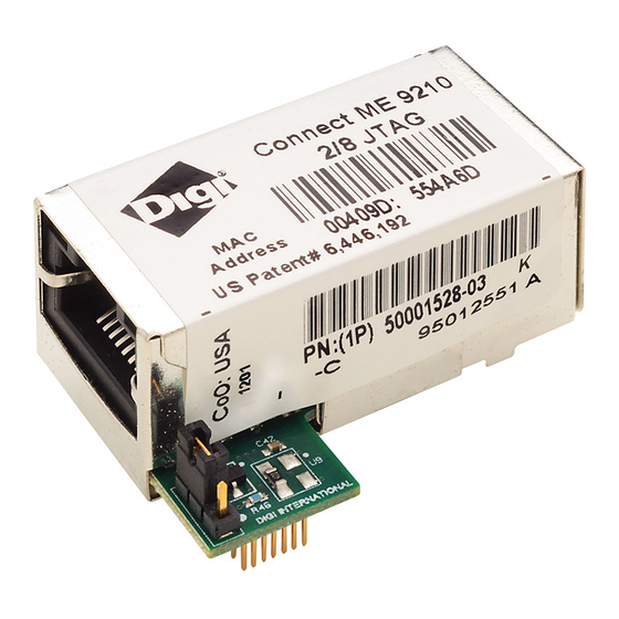
Page 10: Types Of Modules
T y p e s o f m o d u l e s Types of modules The type of module that you will use for hardware integration depends on the kit you are using. If you are using an integration kit, you will be using a module without a JTAG interface. -
Page 11: Dimensions
A b o u t t h e D i g i C o n n e c t M E M o d u l e Dimensions The following figures show the dimensions of Digi Connect ME embedded module. .750... -
Page 12: Recommended Pcb Layout
1.150 29,21 1.216 30,87 .300 [7,62] Dimensions: Side View Recommended PCB layout The following figure shows the recommended PCB (printed circuit board) layout of the Digi Connect ME embedded module. SHIELD OUTLINE .815 .050 .070 [20,701] [1,27] [1.778] .450 .720 [11,43] .050... -
Page 13: Connectors: Power And Device Interface
230,400 bps and full-modem control, and GPIO ports. See the following figure for pin orientation and the table for pin assignments. Digi recommends 100 pF capacitors to ground on all inputs and outputs to the Note module for ESD immunity. This does not apply to the power pass-thru pins. - Page 14 Request to Send (Output) / GPIO — Reserved. Do not connect DTR / GPIO 5 Data Terminal Ready (Output) / GPIO /INIT GPIO--See "Digi Connect ME GPIO pin use" on page 31 and "Reset" on page 33. Power and Device Interface Connector Pin Assignments...
-
Page 15: Connectors: Ethernet Interface
A b o u t t h e D i g i C o n n e c t M E M o d u l e Connectors: Ethernet interface The Ethernet connector is an 8-wire RJ-45 jack that meets the ISO 8877 requirements for 10/100BASE-T. -
Page 16: Leds
L E D s LEDs The module has two LEDs that are located near the upper corners of the Ethernet port (see the following figure). The following table describes the LEDs. The LEDs are the same for a module with or without a JTAG connector. Note Network Network Activity/... -
Page 17: Chapter 2: About The Development Board
Overview The development board is a hardware platform from which you can determine how to integrate the Digi Connect ME embedded module into your design. The board consists of the following main features: Socket for connecting the Digi Connect ME embedded module... -
Page 18: Basic Description
The development board contains connectors, switches, and LEDs for use while integrating the Digi Connect ME embedded module into your design. See the following figure for the location of the connectors, switches, and LEDs. Additionally, the board provides test points (not shown on the figure). - Page 19 GPIO Switch Bank, SW2 Digital Signal Monitor Jack, P6 JTAG Header, P4 LEDs, CR15 and CR16 Jumper Block, P12 (Reserved) Reset Switch, SW3 Digi Connect ME embedded LED, CR17 module Connector, P7 Digi Connect ME embedded Power Jack, P11 module JTAG Connector, P8...
-
Page 20: Port Descriptions
P o r t d e s c r i p t i o n s Module with JTAG connector—for use with a development kit See the following figures for placement of either module onto the development board. Module with JTAG connector Development board... - Page 21 A b o u t t h e D e v e l o p m e n t B o a r d Primary serial port, P1 The Primary Serial Port is a DB-9 male connector that is labeled as P1 on the development board.
- Page 22 The Secondary Serial Port is a DB-9 male connector that is labeled as P2 on the development board. The port is used only with the Digi Connect ME modules with JTAG interfaces (in the development kit) for debugging purposes. See the following figure for pin orientation;...
- Page 23 A b o u t t h e D e v e l o p m e n t B o a r d GPIO port, P3 The GPIO port is a 10-pin male right-angle connector that is labeled as P3 on the development board.
-
Page 24: Connectors And Blocks
Digi Connect ME embedded module connector, P7 The Digi Connect ME embedded module Connector is a 20-pin female vertical header that is labeled P7 on the development board. The connector is used with the integration kit and the development kit. See the following figure for pin orientation; see the following table for pin assignments. - Page 25 RESET Reset +3.3V Power Ground — Reserved. Do not connect. — Reserved. Do not connect. — Reserved. Do not connect. /INIT GPIO--See "Digi Connect ME GPIO pin use" on page 31 and "Reset" on page 33 Module Connector Pin Assignments...
- Page 26 The Module JTAG Interface Connector is a 14-pin female vertical header that is labeled P8 on the development board. The connector mates with the JTAG connector on the Digi Connect ME embedded module. The Module JTAG Connector pins are tied to the JTAG debugger Connector (see “JTAG debugger connector, P4”).
- Page 27 A b o u t t h e D e v e l o p m e n t B o a r d Signal Signal VCC+ TCKRXD /TRST ICETRST VCC+ Pin Assignments JTAG Debugger Connector Jumper block, P12 This jumper block is reserved for future use. Digital Signal Analyzer Header, P6 The Digital Signal Analyzer Header is a 16-pin male vertical header that is labeled P6 on the development board.
- Page 28 C o n n e c t o r s a n d b l o c k s Pin 1 Pin 2 Pin 20 Pin 19 Digital Signal Analyzer Header Pin Orientation Signal Signal Not connected GPIO-5 Not connected TXD2 Not connected GPIO-4...
-
Page 29: Switches
The following sections describe the switches. GPIO switch bank 1, SW1 GPIO Switch Bank 1, labeled SW1, is a set of five slide switches that allows the Digi Connect ME embedded module to use either serial signals or GPIO signals to communicate with a device. - Page 30 Reset, SW3 The Reset switch is a push button switch labeled SW3 on the development board. Pressing the switch holds the Digi Connect ME embedded module in reset. When the push button is released, the module reboots. D i g i C o n n e c t M E H a r d w a r e R e f e r e n c e...
-
Page 31: Leds
A b o u t t h e D e v e l o p m e n t B o a r d LEDs The development board contains 17 LEDs that are labeled CR1 through CR17. The following table lists and describes the LEDs. Board Description Color or State... - Page 32 L E D s Board Description Color or State Indication Label RTS, Primary Serial Port Yellow Active Green Inactive Not connected or signal not being driven DCD, Primary Serial Port Yellow Active Green Inactive Not connected or signal not being driven DSR, Primary Serial Port Yellow Active...
- Page 33 A b o u t t h e D e v e l o p m e n t B o a r d Board Description Color or State Indication Label CR14 GPIO-5 Input/Output Logic high Logic low CR15 3.3V Indicator Power on Power off CR16...
-
Page 34: Power Jack
P o w e r j a c k Power jack The Power Jack is a barrel connector that accepts 9 to 30 VDC +/- 5%. The jack is labeled as P11 on the development board. The following table shows the polarity of the power jack. Contact Polarity Center... -
Page 35: Test Points
A b o u t t h e D e v e l o p m e n t B o a r d Test points The development board provides 24 test points that can be identified by board label or test point number. - Page 36 T e s t p o i n t s D i g i C o n n e c t M E H a r d w a r e R e f e r e n c e...
-
Page 37: Chapter 3: Programming Considerations
Programming Considerations Overview This chapter provides information programmers may require to make use of some Digi Connect ME hardware resources. It provides information on the following topics: "GPIO" on page 30 "LEDs" on page 32 "Reset" on page 33 "Flash" on page 34... -
Page 38: Gpio
G P I O GPIO General information The NS7520 processor supports 16 general purpose I/O (GPIO) lines, some of which are reserved for specific functions and some of which can be customized. These GPIO lines fall into three categories: Those labeled “Reserved” in the following table are reserved for a specific use and must not be reprogrammed, or the unit might not operate correctly. - Page 39 P r o g r a m m i n g C o n s i d e r a t i o n s Digi Connect ME GPIO pin use Name Register Category External Description Interface Serial PORTA7 Allocated Pin 8 on the 20 Used for serial transmit.
-
Page 40: Leds
Reserved PORTC0 LEDs General information The Digi Connect ME has two types of LEDs: An LED connected directly to GPIO pins on the processor and controlled directly in software An LED connected to other hardware components (normally the Ethernet hardware) and not directly programmable by the operating system The development kit, by default, correctly configures the GPIO connected to the LED (PORTC6) as an output and then uses this LED to represent Ethernet activity. -
Page 41: Reset
One choice is to use a GPIO pin as a signal to trigger a soft reset. The Digi Connect ME has one GPIO pin named "/INIT” (PORTC5) that is not normally assigned to any other task. It is an ideal candidate for a soft reset. -
Page 42: Flash
Flash General information Logical regions with Digi Connect ME flash are assigned to particular uses. As a result, its use for general purposes in development kit applications is limited. In particular, the flash file system region can be used for general purposes if the BSP is not configured to create the flash files system, and all but the first sector of the NVRAM region can be used since the Net+OS NVRAM parameters currently (easily) fit into one sector. -
Page 43: Appendix A Module Specifications
Module Specifications Mechanical Length: 1.445 in. (36.703 mm) Width: 0.75 in. (19.05 mm) Height: 0.735 in. (18.669 mm) Device/serial interface connector: 20-pin micro header (10-pin double row) with .50-inch (1.27-mm) pitch (Samtec P/N FTS-110-01-F-DV-TR or similar). Positions 3 through 6 are removed. Environmental Ambient Temperature: -40 F to 185... -
Page 44: Network Interface
N e t w o r k i n t e r f a c e Network interface RJ-45 connector (8-pin) 10/100BASE-T Half-duplex and full-duplex support Cable: A shielded RJ-45 cable must be used to connect the module to the network. -
Page 45: Gpio
M o d u l e S p e c i f i c a t i o n s GPIO Five GPIO (General Purpose Input/Output) ports are selectable between modem control and GPIO as follows: RTS/GPIO 4 DTR/GPIO 5 CTS/GPIO 2 DCD/GPIO 1 DSR/GPIO 3... - Page 46 D C c h a r a c t e r i s t i c s Symbol Description Unit Input High Voltage — 3.45 -0.3 0.2*V Input Low Voltage — Inputs Symbol Description Unit Output High Voltage — 3.45 Output Low Voltage —...
-
Page 47: Appendix B Certifications
FCC Part 15 Class B Radio frequency interference (RFI)(FCC 15.105) The Digi Connect ME embedded module has been tested and found to comply with the limits for Class B digital devices pursuant to Part 15 Subpart B, of the FCC Rules. These limits are designed to provide reasonable protection against harmful interference in a residential environment. -
Page 48: Industry Canada
Modifications (FCC 15.21) Changes or modifications to this equipment not expressly approved by Digi may void the user's authority to operate this equipment. Industry Canada This digital apparatus does not exceed the Class B limits for radio noise emissions from digital apparatus set out in the Radio Interference Regulations of the Canadian Department of Communications. -
Page 49: Declaration Of Conformity
The product listed above has been tested at an External Test Laboratory certified per FCC rules and has been found to meet the FCC, Part 15, Class B, Emission Limits. Documentation is on file and available from the Digi International Homologation Department. -
Page 50: International Emc Standards
I n t e r n a t i o n a l E M C s t a n d a r d s International EMC standards The Digi Connect ME embedded module meets the following electromagnetic emissions standards:... - Page 52 PN:(1P) 90000318 B...
Need help?
Do you have a question about the Connect ME and is the answer not in the manual?
Questions and answers