Fleck 5600 Service Manual
Hide thumbs
Also See for 5600:
- Service manual (31 pages) ,
- Installation instructions manual (19 pages) ,
- Installation manual (11 pages)

Related Manuals for Fleck 5600


Summary of Contents for Fleck 5600
- Page 1 MODEL 5600 & 5600 ECONOMINDER ® Service Manual IMPORTANT: Fill in pertinent information on page 2 for future reference.
-
Page 2: Job Specification Sheet
MODEL 5600 & 5600 ECONOMINDER ® Job Specification Sheet • JOB NO. __________________________________________________________ • *MODEL NO. ______________________________________________________ • WATER TEST ______________________________________________________ • CAPACITY PER UNIT_____________ MAX. ___________PER REGENERATION • MINERAL TANK SIZE DIA.________ HEIGHT _________ • BRINE TANK SIZE & SALT SETTING PER REGENERATION: •... -
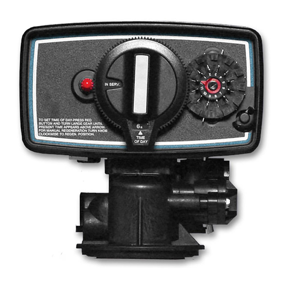
Page 3: Installation And Start-Up Procedure
MODEL 5600 Installation and Start-Up Procedure The water softener should be installed with the inlet, outlet and drain connections made in accordance with manufacturer’s recommendations and to meet applicable plumbing codes. MANUAL 24 HOUR GEAR REGENERATION KNOB SKIPPER WHEEL (SHOWS EVERY... - Page 4 MODEL 5600 Control Valve Drive Assembly (See opposite page for parts list) Page 4 Printed in U.S.A.
- Page 5 MODEL 5600 Control Valve Drive Assembly Parts List Item No. Quantity Part No. Description 1 ... . 1 ... . . 14448-010 ....Housing - w/Pin 1 .
- Page 6 MODEL 5600 & 5600 ECONOMINDER ® Control Valve Drive Assembly For (Clock Or Meter) (See opposite page for parts list) BACKWASH FILTER INJECTOR OPTION Page 6 Printed in U.S.A.
- Page 7 MODEL 5600 & 5600 ECONOMINDER ® Control Valve Drive Assembly For (Clock Or Meter) Parts List Item No. Quantity Part No. Description 1 ... . . 2-4 ... . .13255 ..... Adapter Clip (clock or meter) 2 .
- Page 8 MODEL 5600 BACKWASH FILTER Installation and Start-Up Procedure MANUAL BACKWASH 24 HOUR GEAR KNOB SKIPPER WHEEL SHOWS EVERY RED TIME OTHER DAY BACKWASH BUTTON TIME OF DAY RED POINTER ARROW 1. The filter should be installed with the inlet, outlet, and Set the days backwashing is to occur by sliding tabs on the skipper wheel outward to expose trip fingers.
- Page 9 MODEL 5600 ECONOMIDER ® Installation and Start-up Procedure (Cont’d.) The water softener should be installed with the inlet, outlet and drain connections made in accordance with manufacturer’s recommendations and to meet applicable plumbing codes. MANUAL REGENERATION 24 HOUR GEAR KNOB...
- Page 10 MODEL 5600 ECONOMINDER ® Control Valve Drive Assembly (See opposite page for parts list) Page 10 Printed in U.S.A.
-
Page 11: Parts List
MODEL 5600 ECONOMINDER ® Parts List Item No. Quantity Part No. Description 1 ... . 1 ... . . 14448-000 ....Housing - with Roll Pin 1 . -
Page 12: By-Pass Valve Assembly, Plastic
MODEL 5600 & 5600 ECONOMINDER ® By-Pass Valve Assembly, Plastic Item No. Quantity Part No. Description 1 ... 1 ... . 19723....By-Pass Valve Body, Plastic 2 . -
Page 13: Meter Assembly
MODEL 5600 ECONOMINDER ® Meter Assembly Item No. Quantity Part No. Description 1 ... 4 ... 12473 ....Screw - Meter Cover Assembly 2A . -
Page 14: By-Pass Valve Assembly
MODEL 5600 & 5600 ECONOMINDER ® By-Pass Valve Assembly Item No. Quantity Part No. Description 1 ... 1... . 17290....By-Pass Valve Body, 3/4″... - Page 15 60086 ..Meter, Std. 60087 ..Meter, Ext. 60136-5600 ..Service Kit, Meter 60135-5600 ..Service Kit, Clock 14860 .
-
Page 16: Water Conditioner Flow Diagrams
MODEL 5600 & 5600 ECONOMINDER ® Water Conditioner Flow Diagrams SERVICE POSITION PRELIMINARY RINSE POSITION 5 Minutes Hard water enters the unit at the valve inlet - flows Hard water enters the unit at the valve inlet - flows around... - Page 17 MODEL 5600 & 5600 ECONOMINDER ® Water Conditioner Flow Diagrams (Cont’d.) BACKWASH POSITION BRINE POSITION 10 Minutes First Portion of 50 Minute Fixed Cycle Hard water enters the unit at the valve inlet - flows Hard water enters the unit at the valve inlet - flows around...
- Page 18 MODEL 5600 & 5600 ECONOMINDER ® Water Conditioner Flow Diagrams (Cont’d.) SLOW RINSE POSITION RAPID RINSE POSITION Last Portion of 50 Minute Fixed Cycle 10 Minutes Hard water enters the unit at the valve inlet - flows After all the brine has been drawn from the brine...
- Page 19 MODEL 5600 & 5600 ECONOMINDER ® Water Conditioner Flow Diagrams (Cont’d.) SETTLING RINSE POSITION BRINE TANK FILL POSITION 5 Minutes 4 to 24 Minutes Adjustable Cycle Hard water enters the unit at the valve inlet - flows around Hard water enters the unit at the valve inlet - flows...
-
Page 20: Troubleshooting
MODEL 5600 & 5600 ECONOMINDER ® Trouble-Shooting PROBLEM CAUSE CORRECTION Softener fails to regenerate. Electrical service to unit has been Assure permanent electrical ser- interrupted. vice (check fuse, plug, pull chain or switch). Timer is defective. Replace timer. C. Power failure. - Page 21 MODEL 5600 & 5600 ECONOMINDER ® Trouble-Shooting (Cont’d.) PROBLEM CAUSE CORRECTION 8b. Salt water in service line Plugged injector system. Clean injector and replace screen. Timer not cycling. Replace timer. C. Foreign material in brine valve. C. Clean or replace brine valve.
- Page 22 MODEL 5600SF Trouble-Shooting PROBLEM CAUSE CORRECTION Filter fails to backwash. Electrical Service to unit has been Assure Permanent Electrical Ser- interrupted. vice (Check Fuse, Plug, Pull Chain or Switch). Timer is Defective. Replace or replace timer. C. Power Failure. C. Reset time of Day. Filter “bleeds”...
- Page 23 MODEL 5600 & 5600 ECONOMINDER ® Service Instructions A. TO REMOVE TIME BRINE VALVE, INJECTORS, AND 11. Check for leaks at all seal areas. Check drain seal SCREEN with the control in the backwash position. Unplug electrical cord from outlet.
- Page 24 MODEL 5600 & 5600 ECONOMINDER ® Service Instructions (Cont’d.) C. TO REPLACE PISTON ASSEMBLY D. TO REPLACE SEALS AND SPACERS Unplug electrical cord from outlet. Unplug electrical cord from outlet. Turn off water supply to conditioner: Turn off water supply to conditioner: a.
- Page 25 MODEL 5600 & 5600 ECONOMINDER ® Service Instructions (Cont’d.) 10. Push resin tank back to the plumbing connections Relieve water pressure in the conditioner by putting and engage meter ports with by-pass valve or yoke. the control in the backwash position momentarily.
- Page 26 Notes Page 26 Printed in U.S.A.
- Page 28 P/N 40106 Rev. 6 4/01...
Need help?
Do you have a question about the 5600 and is the answer not in the manual?
Questions and answers
Dont have a 110 outlet, old 5600 unit used a transformer wire new units have a 110 pulg connected to the unit, how do i hook up the new units to the transformer wire?
Softener is working but the water is not soft enough. Residue on glass and surfaces, water taste of iron ,soap does not lather. How do we change flow to get softer water.