
Related Manuals for Exmark LAZER Z X Series


Summary of Contents for Exmark LAZER Z X Series
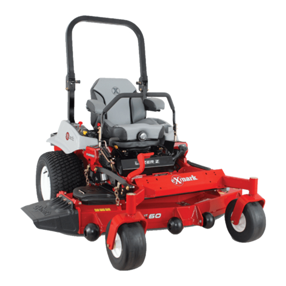
- Page 1 LAZER Z ® For Serial Nos. 316,000,000 & Higher Lazer Z (LZE, LZS, LZX) Units Part No. 4502-754 Rev. A...
- Page 2 SAE testing and gross/net power rating standards (J1940, J1995, J1349). Exmark reserves the right to make changes or add improvements to its products at any time without incurring any obligation to make such changes to products manufactured previously.
-
Page 3: Introduction
All Exmark parts are thoroughly tested and inspected before leaving the factory, however, attention is required on your part if you are to obtain the fullest measure of satisfaction and performance. -
Page 4: Table Of Contents
Contents Motion Control Linkage Adjustment ....55 Motion Control Damper Adjustment....56 Motion Control Neutral Lock Pivot Introduction ............3 Adjustment ..........56 Safety ..............5 Motion Control Handle Adjustment ....57 Safety Alert Symbol ......... 5 Motion Control Full Forward Tracking Safe Operating Practices ........5 Adjustment ..........57 Safety and Instructional Decals ......11 Caster Pivot Bearings Pre-Load... -
Page 5: Safety
Institute in effect at the time of production. explain this material to them; other languages may be available on our website. Exmark designed and tested this lawn mower to offer reasonably safe service; however, failure to comply • Become familiar with the safe operation of the with the following instructions may result in personal equipment, operator controls, and safety signs. - Page 6 Safety • Inspect the area where the equipment is to be DANGER used and remove all rocks, toys, sticks, wires, In certain conditions during fueling, static bones, and other foreign objects which can be electricity can be released causing a spark thrown by the machine and may cause personal which can ignite gasoline vapors.
- Page 7 Safety X and S-Series Models: • Never mow with the discharge deflector raised, removed or altered unless there is a grass CAUTION collection system or mulch kit in place and working properly. Fuel tank vent is located inside the roll •...
- Page 8 Safety • Use extreme care when loading or unloading the machine into a trailer or truck. • Use care when approaching blind corners, shrubs, trees, or other objects that may obscure vision. Slope Operation Use Extreme caution when mowing and/or turning on slopes as loss of traction and/or tip-over could occur.
- Page 9 • Ventilate when charging or using battery • Any accessories, alterations, or attachments added in an enclosed space. to the ROPS must be approved by Exmark. • Make sure venting path of battery is Maintenance and Storage always open once battery is filled with acid.
- Page 10 Unauthorized modifications to the original For Kohler EFI (Electronic Fuel Injection) Units: equipment or failure to use original Exmark parts could lead to serious injury or death. WARNING Unauthorized changes to the machine, engine,...
-
Page 11: Safety And Instructional Decals
Exmark equipment dealer or labels. distributor or from Exmark Mfg. Co. Inc. • Replace all worn, damaged, or missing safety • Safety signs may be affixed by peeling off the signs. - Page 12 Safety 109-6036 1. Read the Operator’s manual 2. Remove the ignition key and read the instructions before servicing or performing maintenance. 3. Height of cut 112-9028 107-3069 1. Warning—stay away from moving parts; keep all guards 1. Warning-there is no rollover protection when the roll bar in place.
- Page 13 Safety 114-4466 1. Main, 25A 3. Charge, 25A 2. PTO, 10A 4. Auxiliary, 15A 116-8724 115-9625 All Units except EFI 1. Parking 2. Parking brake—engaged 1. Throttle-fast 4. Choke-off brake—disengaged 2. Throttle-slow 5. PTO 3. Choke-on 116-4858 116-8725 EFI Units Only 116-8283 1.
- Page 14 Safety 116-8726 1. Read the Operator’s Manual for recommended hydro oil. 116-8727 117-0346 1. Fuel leak hazard—read the Operator's Manual; do not attempt to remove the roll bar; do not weld, drill or modify the roll bar in any way. 117-3864 1.
- Page 15 Safety 126-0768 Rear Discharge Units Only 126-4108 EFI Red Equipped Units Only 1. Engine oil temperature 5. Throttle-efficient setting; engine rotational speed 126-2055 standard idle speed-fuel economy 1. Wheel lug nut torque 95 ft-lb (129 N-m) (4x) 2. Engine oil pressure 6.
- Page 16 Safety 126-6599 1. Thrown objects hazard 2. Cutting/dismemberment 126-4398 - keep bystanders a of hand - stay away from safe distance from the moving parts; keep all 1. Read the Operator’s 3. Unlock machine. guards and shields in manual place. 2.
- Page 17 Safety PTO Switch Symbols 1. PTO–disengage 2. PTO–engage Message Display 1. Fuel 6. Hour meter 2. Empty 7. PTO 3. Half 8. Parking brake 4. Full 9. Neutral 5. Battery 10. Operator presence switch 132-0871 4. Ramp hazard—when loading onto a trailer, do not use 1.
- Page 18 Safety 132-5080 “B1”, “B2”, and “B3” Models Only 1. Firmest position 2. Softest position...
-
Page 19: Specifications
• Fuel level eight segment display — right hand control panel. • Engine Specifications: See your Engine Owner’s • Low fuel indicator light. Manual • Engine Oil Type: Exmark 4–Cycle Premium Electrical System Engine Oil • Charging System: Flywheel Alternator • RPM: •... - Page 20 Specifications Note: Motion control levers are adjustable to – “A1” and “A2” Models: two heights. Deluxe suspension (adjustable spring suspension) – Separate levers, on each side of the console, seat with high back, padded flip-up armrests, and control speed and direction of travel of the integral safety switch.
- Page 21 ◊ 16cc Parker axial piston pump Size (52 Deck) 13 x 5.00-6 ◊ 280cc Parker geroler motor S-Series: • Hydraulic Oil Type: Exmark Premium Hydro Oil. • Hydraulic Oil Capacity: 52 oz (1.5 L) per side Drive Pneumatic (Air filled) • Hydraulic Filter: P/N 116-0164 Deck Size 48 &...
- Page 22 Specifications • Discharge: Front Caster – Side Discharge: Non “R” models Semi-Pneumatic – Rear Discharge: “R” models Deck Size “00” “A2” “A1” Models Models Models • Blade Size: (3 ea.) Quantity – 48 inch Deck: 16.25 inches (41.3 cm) Smooth Smooth Smooth –...
-
Page 23: Dimensions
Specifications Dimensions Overall Height: All Models Except “B1”, “B2”, and “B3” Overall Width Roll Bar - Up Roll Bar - Down Side Discharge Units: 70.5 inches (179.1 cm) 46.8 inches (118.9 cm) 48 inch Deck 52 inch Deck “B1”, “B2”, and “B3” Models Without Deck 45.7 inches 45.7 inches... - Page 24 Specifications Accessory Weight Table Worksheet: Curb Weight: Units with 48 Inch Side 1080–1160 lb Use the table below to determine if extra weight Discharge Decks (490– 526 kg) is required for the unit. Identify the accessories and correct deck size and place the corresponding Units with 52 Inch Side 1100–1220 lb values in the Accessory Score column.
-
Page 25: Torque Requirements
Specifications second under toe board kit for secondary accessory Bolt Location Torque weighting (scores 20 and higher). Suspension Platform Rear 15-19 ft-lb (20-26 N-m) Cross Shaft 5/16 inch * 60 inch units that have an under toe board mount Retention Bolt weight as standard, require 116-1238 front toe board top mount kit instead of 116-1173. -
Page 26: Product Overview
Operation Product Overview Operation Note: Determine the left and right sides of the machine from the normal operating position. Controls Motion Control Levers The motion control levers located on each side of the console control the forward and reverse motion of the machine. - Page 27 Operation Figure 6 Right Console 1. Fuses 4. PTO engagement switch 2. Message display 5. Throttle 3. Ignition switch 6. Choke Throttle Control Figure 5 (All Units Except EFI RED Equipped 1. Neutral lock position 4. Forward Units) (handles out) 2.
- Page 28 Operation The brake lever engages a parking brake on the drive wheels. Note: The LCD indicator appears in the message display on the RH console when the park brake is engaged (see Figure 9). Pull the lever up and rearward to engage the brake. Push the lever forward and down to disengage the brake.
- Page 29 Operation Drive Wheel Release Valves WARNING Hands may become entangled in the rotating drive components below the engine deck, which could result in serious injury or death. Stop engine, remove key, allow all the moving parts to stop before accessing the drive wheel release valves.
- Page 30 Operation Note: The handle must be horizontal and against Position in the transport latching position to the stop for operation. automatically latch the cutting deck when raised to the transport position (see item 1 in Figure 11). Do Not tow machine. In the non-latching position, the deck will automatically return to the cutting height when the PTO Engagement Switch...
-
Page 31: Pre-Start
Operation High Oil Temperature Warning Light interlock partially. Apply forward pressure to the (EFI RED Equipped Units Only) roll bar upper hoop and observe that the knobs return to the completely latched position. Located in the right console panel–the left light below the throttle control. - Page 32 Operation Open the Fuel Shut-Off Valve DANGER Rotate the valve and align with the fuel line to open. An uncovered discharge opening will allow objects to be thrown in an operator’s or bystander’s direction. Also, contact with the Starting the Engine blade could occur.
- Page 33 Operation 5. Disengage the PTO. 6. Allow the engine to run for a minimum of 15 seconds, then turn the ignition switch to the “OFF” position to stop the engine. 7. Remove the key to prevent children or other unauthorized persons from starting engine. 8.
- Page 34 Operation To turn right, release pressure on the RH motion control lever and the rear of the machine will move towards the rear and to the right. To turn left, release pressure on the LH motion control lever and the rear of the machine will move towards the rear and to the left.
- Page 35 Operation See the decal on the side of the deck lift plate for of the bolt and the mounting bracket (see cut heights. Figure 19). 6. Push the deck lift pedal, release the transport lock B. Torque the 3/8 nyloc nut to 50–55 ft-lb and allow the deck to lower to the cutting height.
- Page 36 Operation Adjusting the Side Bumpers Adjusting the Suspension Seat For (Rear Discharge Units Only) “B1”, “B2”, and “B3” Models Only Mount the side bumpers in the top holes when The suspension system adjusts to provide a smooth operating in height of cuts higher than 2 1/2 inches and comfortable ride.
- Page 37 Operation Figure 23 1. Firmest position 3. Detents in the slots 2. Softest position Note: Ensure the left and right rear, shock assemblies are always adjusted to the same positions. Adjust the rear, shock assemblies (Figure 24). g030019 Figure 24 •...
-
Page 38: Transporting
Operation Loading the Machine To adjust the front, shock assembly, open the floor pan and adjust it by using a spanner wrench (Part Use extreme caution when loading or unloading No. 132–5069) or a slip-joint pliers (Figure 25). machines onto a trailer or a truck. Use a full-width ramp that is wider than the machine for this procedure. - Page 39 Operation WARNING Loading a machine onto a trailer or truck increases the possibility of tip-over and could cause serious injury or death. • Use extreme caution when operating a machine on a ramp. • Ensure that the ROPS is in the up position and use the seat belt when loading or unloading the machine.
-
Page 40: Maintenance
Maintenance Maintenance Note: Determine the left and right sides of the machine from the normal operating position. WARNING WARNING While maintenance or adjustments are being The engine can become very hot. Touching a hot made, someone could start the engine. engine can cause severe burns. -
Page 41: Periodic Maintenance
“FULL” the hours are normally displayed. Locate the voltage mark on the dipstick. Exmark 4-Cycle Premium reading of the battery in the table and charge the Engine Oil is recommended; refer to the Engine... - Page 42 Maintenance Voltage Percent Maximum Charging CAUTION Reading Charge Charger Interval Connecting the jumper cables incorrectly Settings (wrong polarity) can immediately damage the 2 Hours 12.0–12.2 25–50% 14.4 volts/4 electrical and/or EFI system. amps Be certain of battery terminal polarity and 11.7–12.0 0–25% 3 Hours...
-
Page 43: Check Mower Blades
Maintenance Check Mower Blades Service Interval: Before each use or daily 1. Stop engine, wait for all moving parts to stop, and remove key. Engage parking brake. 2. Lift deck and secure in raised position as stated in the Clean Grass Build-Up Under Deck section. 3. -
Page 44: Check Safety Interlock System
Check Safety Interlock Note: If machine does not pass any of these tests, System do not operate. Contact your authorized EXMARK SERVICE DEALER. Service Interval: Before each use or daily Important: It is essential that operator safety... -
Page 45: Check Seat Belt
Maintenance Engine Owner's Manual for additional information.) 1. Stop engine, wait for all moving parts to stop, and remove key. Engage parking brake. 2. See the Engine Owner's Manual for maintenance instructions. Check Air Filter Assembly (if equipped) Figure 32 Service Interval: As required 1. -
Page 46: Check Hydraulic Oil Level
Before reinstalling new filter, apply a thin coating 1. Full 2. Add of Exmark 4–Cycle Premium Engine oil on the surface of the rubber seal. Turn filter clockwise Note: The oil level on the dipstick will be until rubber seal contacts the filter adapter then incorrect if the oil is checked when the unit is hot. -
Page 47: Lubricate Grease Fittings
7. Insert one bearing, one new seal into the wheel. Note: Seals (Exmark P/N 103-0063) must be replaced. 8. If the axle assembly has had both spacer nuts removed (or broken loose), apply a thread locking adhesive to one spacer nut and thread onto the axle with the wrench flats facing outward. -
Page 48: Lubricate Deck Lift Pivot
1. Stop engine, wait for all moving parts to stop, and thereafter) remove key. Engage parking brake. Note: Only use Exmark Hydro Filter–Part No. 2. Lubricate deck lift pivot with a spray type 116-0164 for summer or winter. lubricant or light oil. -
Page 49: Wheel Hub - Slotted Nut Torque Specification
(if equipped) 7. Before installing the new filters, apply a thin coat Service Interval: Every 50 hours of Exmark Premium Hydro Oil on the surface of the two rubber seals. WARNING 8. Install the new filters and torque to 14 ft-lb (19 Hot exhaust system components may ignite N-m). -
Page 50: Copper-Based Anti-Seize
Maintenance Adjustments Copper-Based Anti-seize Copper-based anti-seize is used in the following Note: Disengage PTO, shut off engine, wait for location: all moving parts to stop, engage parking brake, and remove key before servicing, cleaning, or making any On threads of Blade Bolts. See Check Mower adjustments to the unit. - Page 51 Maintenance 7. Release the transport lock and allow the deck to lower to the cutting height. 8. Raise the discharge deflector (side discharge units only). 9. Measure from the level surface to the front tip of the center blade. The measurement should read 3 inches (7.6 cm).
-
Page 52: Pump Drive Belt Tension
Maintenance • Side Discharge Units: The back tips of the side blades should measure 3 1/4 inches (8.3 cm). • Rear Discharge Units: The back tips of the side blades should measure 3 inches (7.6 cm). 12. Re-measure until all four sides are the correct height. - Page 53 Maintenance Check to make sure brake is adjusted properly. This procedure must be followed after the first 100 hours or when a brake component has been removed or replaced. 1. Drive the machine onto a level surface. 2. Disengage the blade control switch (PTO), move the motion control levers to the neutral locked position and engage the parking brake (lever is in the “up”...
-
Page 54: Electric Clutch Adjustment
Maintenance Electric Clutch Adjustment No adjustment necessary. However on units with 60 inch decks, when the clutch brake has worn to the point where the clutch no longer engages consistently, the shim can be removed to extend the clutch life. Figure 44 1. -
Page 55: Motion Control Linkage Adjustment
Maintenance WARNING Engine must be running and drive wheels must be turning so adjustments can be performed. Contact with moving parts or hot surfaces may cause personal injury. Keep fingers, hands, and clothing clear of rotating components and hot surfaces. 1. -
Page 56: Motion Control Damper Adjustment
Maintenance Figure 47 1. Double nuts Figure 48 RH Motion Control Shown 8. Shut off unit. Remove jumper wire from wire harness and plug connector into seat switch. 1. Torque nyloc nut to 200 in-lb (16.7 ft-lb). Bolt must protrude past end of nyloc nut after torque. A T-40 Torx 9. -
Page 57: Motion Control Handle Adjustment
Maintenance Motion Control Handle 1. Loosen the screws on a cover plate (see Figure 51). Adjustment 2. Slide the cover plate backward or forward to adjust the travel of the lever and tighten the Adjusting the height: screws. The motion control levers can be adjusted higher or 3. -
Page 58: Cleaning
Maintenance Cleaning Clean Engine and Exhaust System Area Service Interval: Before each use or daily (May be required more often in dry or dirty conditions.) CAUTION Excessive debris around engine cooling air intake and exhaust system area can cause engine, exhaust area, and hydraulic system to overheat which can create a fire hazard. -
Page 59: Clean Debris From Machine
Maintenance Cleaning the Suspension system to run cooler and improve the life of the hydro system. System 1. Stop engine, wait for all moving parts to stop, and Note: Do not clean the shock assemblies with remove key. Engage parking brake. pressurized water. -
Page 60: Troubleshooting
Troubleshooting Troubleshooting Important: It is essential that all operator safety mechanisms be connected and in proper operating condition prior to mower use. When a problem occurs, do not overlook the simple causes. For example: starting problems could be caused by an empty fuel tank. The following table lists some of the common causes of trouble. - Page 61 Troubleshooting Problem Possible Cause Corrective Action Oil pressure light is on and engine RPM is low 1. Engine Control Unit has limited engine 1. Let engine cool and check oil level. If level RPMs, known as “limp” mode. is above “add”, contact an Authorized Service Dealer.
- Page 62 Troubleshooting Problem Possible Cause Corrective Action Clutch will not engage. 1. Fuse is blown. 1. Replace fuse. Check coil resistance, battery charge, charging system, and wiring connections and replace if necessary. 2. Low voltage supply at the clutch. 2. Check coil resistance, battery charge, charging system, and wiring connections and replace if necessary.
-
Page 63: Schematics
Schematics Schematics Electrical Diagram — All units except Kohler EFI... - Page 64 Schematics Electrical Diagram — Kohler EFI MIL PWR MIL GND ECU PWR ECU PWR GND-S/D WHITE GND-S/D START BLUE START...
- Page 65 Schematics Electrical Diagram — Kohler EFI Red Equipped Units...
- Page 66 Schematics Electrical Logic Schematic — Kawasaki...
- Page 67 Schematics Electrical Logic Schematic — Kohler Carburated...
- Page 68 Schematics Electrical Logic Schematic — Kohler EFI...
- Page 69 Schematics Electrical Logic Schematic — Kohler EFI Red Equipped Units...
- Page 70 Schematics Hydraulic Diagram...
- Page 71 Commercial Warranty Conditions Exmark Customer Service Department This warranty applies to Exmark Lazer Z X-Series, Lazer Z S-Series, and The Exmark Warranty Company Vantage turf equipment sold in the U.S. or Canada for a period of three 2101 Ashland Avenue years for commercial usage.
- Page 72 Commercial Warranty Conditions Exmark Customer Service Department This warranty applies to Exmark Lazer Z E-Series turf equipment sold in The Exmark Warranty Company the U.S. or Canada for a period of two years for commercial usage.
- Page 73 Service Record Date: Description of Work Done: Service Done By:...
- Page 75 G011841 Figure 54 This page may be copied for personal use. 1. The maximum slope you can safely operate the machine on is 15 degrees. Use the slope indicator to determine the degree of slope of hills before operating. Do Not operate this machine on a slope greater than 15 degrees. Fold along the appropriate line to match the recommended slope.
- Page 76 Pack) or Fill in Below Engine Model No. and Spec. No. Model No. Engine Serial No. (E/No) Serial No. ©2015 Exmark Mfg. Co., Inc. Part No. 4502-754 Rev. A Industrial Park Box 808 (402) 223-6300 Beatrice, NE 68310 Fax (402) 223-5489...
Need help?
Do you have a question about the LAZER Z X Series and is the answer not in the manual?
Questions and answers