Exmark LAZER Z XS Operator's Manual
Diesel models
Hide thumbs
Also See for LAZER Z XS:
- Operator's manual (56 pages) ,
- Parts manual (32 pages) ,
- Setup instructions (5 pages)

Related Manuals for Exmark LAZER Z XS


Summary of Contents for Exmark LAZER Z XS
-
Page 1: Diesel Models
LAZER Z ® DIESEL MODELS For Serial Nos. 790,000 & Higher Part No. 4500-501 Rev. A... - Page 2 Replacements may be ordered through the engine manufacturer. Exmark reserves the right to make changes or add improvements to its products at any time without incurring any obligation to make such changes to products manufactured previously.
-
Page 3: Introduction
All Exmark parts are thoroughly tested and inspected before leaving the factory, however, attention is required on your part if you are to obtain the fullest measure of satisfaction and performance. -
Page 4: Table Of Contents
Contents Dielectric Grease........... 38 Adjustments ............. 38 Deck Leveling ..........38 Introduction ............3 Pump Drive Belt Tension....... 39 Safety ..............5 Mule Drive Belt Tension Adjustment ..... 39 Safety Alert Symbol ......... 5 Deck Belt Tension ........40 Safe Operating Practices ........5 Alternator Belt Tension ......... -
Page 5: Safety
• Evaluate the terrain to determine what accessories ALERT! YOUR SAFETY IS INVOLVED! and attachments are needed to properly and safely perform the job. Only use accessories and attachments approved by Exmark. • Wear appropriate clothing including safety glasses, Figure 2 substantial footwear, long trousers, and hearing 1. - Page 6 Safety DANGER WARNING In certain conditions diesel fuel is extremely Diesel fuel is harmful or fatal if swallowed. flammable and vapors are explosive. Long-term exposure to vapors has caused cancer in laboratory animals. Failure to use A fire or explosion from diesel fuel can burn caution may cause serious injury or illness.
-
Page 7: Slope Operation
Safety • Be sure all drives are in neutral and parking brake • Stop the blades, slow down, and use caution when is engaged before starting engine. Use seat belts crossing surfaces other than grass and when with the roll bar in the raised and locked position. transporting the mower to and from the area to be mowed. -
Page 8: Maintenance And Storage
Safety Using the Rollover Protection System (ROPS) A Rollover Protection System (roll bar) is installed on the unit. WARNING There is no rollover protection when the roll bar is down. Wheels dropping over edges, ditches, steep banks, or water can cause rollovers, which may result in serious injury, death or drowning. - Page 9 Safety • Park machine on level ground. Never allow WARNING untrained personnel to service machine. Hydraulic fluid escaping under pressure • Use jack stands to support components when can penetrate skin and cause injury. Fluid required. accidentally injected into the skin must be •...
-
Page 10: Safety And Instructional Decals
Exmark equipment dealer or labels. distributor or from Exmark Mfg. Co. Inc. • Replace all worn, damaged, or missing safety • Safety signs may be affixed by peeling off the signs. - Page 11 Safety 103-2076 103-0223 103-7218 103-0261 103-1798 107-2102...
- Page 12 Safety 107-2112 109-1399 109-0872 109-2219 109-1214 109-2263 109-1215...
- Page 13 Safety 109-2264 109-2478 109-2951 109-3148...
- Page 14 Safety 116-0997 109-6855 109-7949 19426-87881 116-0127 19426-87903 116-0404...
- Page 15 Safety 107-9866 1. Fast 2. Slow 3. Neutral 4. Reverse...
-
Page 16: Specifications
B20 (20% biodiesel, 80% petro diesel). Operator Controls • Fuel Filter: In-line 113 Micron • Steering and Motion Control: Exmark P/N 112-7836. Note: Motion control levers are adjustable to • Fuel Shut-Off Valve: 1/4 turn increments two heights. (“OFF”, right tank, left tank, ) –... -
Page 17: Hydrostatic Ground Drive System
– Blades are driven by one “B” Section belt • Hydraulic Oil Type: Exmark Premium Hydro oil. (w/self-tensioning idler) from transfer shaft on deck to blade spindles. • Hydraulic Oil Capacity: 5.5 qt. (5.2 L) •... -
Page 18: Dimensions
Specifications Dimensions Torque Requirements Bolt Location Torque Overall Width: Blade Drive Sheave 90-110 ft-lb (122-149 N-m) 60 inch 66 inch 72 inch Mounting Nut Deck Deck Deck Cutter Housing Spindle 160-185 ft-lb (217-251 Without 53.5 inches 57.3 inches 61.5 inches N-m) Deck (135.9 cm) -
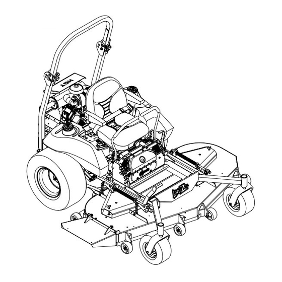
Page 19: Product Overview
Operation Product Overview Operation Note: Determine the left and right sides of the machine from the normal operating position. Controls Motion Control Levers The motion control levers located on each side of the console control the forward and reverse motion of the machine. -
Page 20: Hour Meter
Operation and “START”. Insert key into switch and rotate Drive wheel release valves are used to release the clockwise to the “ON” position. Rotate clockwise to hydrostatic drive system to allow the machine to be the next position to engage the starter (key must be pushed without the engine running. -
Page 21: Pre-Start
Operation The voltmeter measure the voltage output of the Use of summer grade diesel fuel above 20°F (-7°C) alternator. Both high and low voltages will potentially will contribute toward longer life of the pump damage the battery. components. Important: Do Not use kerosene or gasoline Glow Plug Switch and Light instead of diesel fuel. -
Page 22: Operating Instructions
Operation Operating Instructions 2. Pull up and back on the parking brake lever to engage the parking brake. Raise the Rollover Protection System 3. Push in on the PTO switch to the “STOP” position. (ROPS) Note: It is not necessary for the operator to be Important: Lower the roll bar only when in the seat to start the engine. -
Page 23: Driving The Machine
Operation Engaging the PTO 5. Place the throttle midway between the “SLOW” and “FAST” positions. DANGER 6. Allow the engine to run for a minimum of 15 seconds, then turn the ignition switch to the The rotating blades under the mower deck “OFF”... -
Page 24: Adjusting The Cutting Height
Operation Figure 6 1. Handles Out (Neutral 5. Neutral Lock) 2. Handles In (Neutral) 6. Reverse 3. Front of Unit 7. Neutral Lock 4. Forward Figure 7 Driving Forward 1. Handles Out (Neutral 4. Forward Lock) 1. Release the parking brake. 2. -
Page 25: Adjusting The Anti-Scalp Rollers
Operation deck lift assist lever located at the front right 6. Place the rollers in one of the positions shown corner of the floor pan. (Figure 9). Rollers will maintain 3/4 inch (19 mm) clearance to the ground to minimize gouging and Note: When changing the cutting height roller wear or damage. -
Page 26: Transporting
Operation WARNING Loading a unit on a trailer or truck increases the possibility of backward tip-over. Backward tip-over could cause serious injury or death. • Use extreme caution when operating a unit on a ramp. • Use only a single, full width ramp; Do Not use individual ramps for each side of the unit. - Page 27 Operation Important: Do Not attempt to turn the unit while on the ramp, you may lose control and drive off the side. Avoid sudden acceleration when driving up a ramp and sudden deceleration when backing down a ramp. Both maneuvers can cause the unit to tip backward.
-
Page 28: Maintenance
Maintenance Maintenance Note: Determine the left and right sides of the machine from the normal operating position. WARNING WARNING While maintenance or adjustments are being The engine can become very hot. Touching made, someone could start the engine. a hot engine can cause severe burns. Accidental starting of the engine could Allow the engine to cool completely before seriously injure you or other bystanders. -
Page 29: Periodic Maintenance
Maintenance Maintenance Service Maintenance Procedure Interval • Change the hydraulic filter (Every 250 hours/yearly if using Mobil 1 15W50) • Check the wheel hub slotted nut torque specifications. Every 500 hours • Check the wheel lug nuts. • Replace the air cleaner elements. (May need more often under severe conditions. See the Every 600 hours Engine Owner’s Manual for additional information.) •... -
Page 30: Check Mower Blades
A. Install bushing through blade with bushing serious personal injury or death. flange on bottom (grass) side of blade. Always install the original Exmark blades, blade bushings, and blade bolts as shown. Check Safety Interlock System... -
Page 31: Check Rollover Protections Systems (Roll Bar) Pins
See the Engine Owner’s Manual for additional Note: If machine does not pass any of these tests, information.) do not operate. Contact your authorized EXMARK SERVICE DEALER. 1. Stop engine, wait for all moving parts to stop, and remove key. Engage parking brake. -
Page 32: Change Engine Oil
Oil level should be to the top of the 7. Reinstall elements. Position the cover so that the baffle inside the tank. If not, add oil. Use Exmark rubber dust ejector is pointing downward and Premium Hydro oil. Replace hydraulic reservoir secure with retaining clips. -
Page 33: Lubricate Grease Fittings
Maintenance 3. Remove left and right belt shields on deck and lift up floor pan to inspect deck drive belt. 4. Check under machine to inspect the mule drive belt. Refer to Mule Drive Belt Tension Adjustment section in Adjustments. Lubricate Grease Fittings Note: See chart for service intervals. -
Page 34: Lubricate Brake Handle Pivot
Service Interval: Every 160 hours 7. Insert one bearing, one new seal into the wheel. 1. Stop engine, wait for all moving parts to stop, and Note: Seals (Exmark P/N 103-0063) must be remove key. Engage parking brake. replaced. 2. Unhook seat latch and tilt seat up. -
Page 35: Change Fuel Filter/Water Separator
Maintenance Change Fuel Filter/Water Important: Before reinstalling new filter, fill it with Exmark Premium Hydro oil and apply Separator a thin coat of oil on the surface of the rubber seal. Service Interval: Every 400 hours/Yearly (whichever comes first) Turn filter clockwise until rubber seal contacts the... -
Page 36: Check Engine Coolant Level
Maintenance Change Engine Coolant 4. Torque the slotted nut to 125 ft-lb (169 N-m). 5. Then tighten nut until the next set of slots line up Service Interval: Every 4,000 hours/Every 4 with the cross hole in shaft. years (whichever comes first) Dex-Cool©... -
Page 37: Thread Locking Adhesives
Maintenance 7. Operate engine until the engine thermostat opens and coolant is circulating through the radiator core. As air is purged from the engine block and the coolant level drops, add additional coolant to the radiator. 8. When the radiator is completely full and no additional coolant can be added, continue running and install the radiator cap. -
Page 38: Copper-Based Anti-Seize
Maintenance Adjustments • Under top cutter housing bearing guard. • Between the jackshaft and bearings and the Note: Disengage PTO, shut off engine, wait for jackshaft and sheaves. all moving parts to stop, engage parking brake, and remove key before servicing, cleaning, or making any Copper-Based Anti-seize adjustments to the unit. -
Page 39: Pump Drive Belt Tension
Maintenance front swivel using locking nut in front of swivel. side engine deck support, is positioned between Repeat for right side. the centers of the two alignment holes in the left support plate (Figure 16 and Figure 17). It 11. Recheck that the 3/4 inch (19 mm) blocks fit just is necessary to adjust the belt tension when the snugly under the brackets and that the tension on center of the bolt head is at or below the center... -
Page 40: Deck Belt Tension
Maintenance be 1/8 inch (3.2 mm) away from the belt, with bolt-end of guide near end of slot (Figure 18). 4. If adjustment is necessary, loosen the bolt securing the belt guide and make proper adjustment. Tighten hardware. Figure 17 1. -
Page 41: Brake Adjustment
Maintenance Electric Clutch Adjustment No adjustment necessary. Reverse Indicator Adjustment 1. Stop engine, wait for all moving parts to stop, and remove key. Engage parking brake. 2. Unhook seat latch and tilt seat forward. 3. Begin with either the left or right motion control lever. -
Page 42: Motion Control Linkage Adjustment
Maintenance Motion Control Linkage Adjustment WARNING Engine must be running and drive wheels must be turning so motion control adjustment can be performed. Contact with moving parts or hot surfaces may cause personal injury. Keep fingers, hands, and clothing clear of Figure 21 rotating components and hot surfaces. -
Page 43: Motion Control Damper Adjustment
Maintenance Caster Pivot Bearings wheel must stop turning or slightly creep in reverse (Figure 22). Pre-Load Adjustment Remove dust cap from caster and tighten nyloc nut until washers are flat and back off 1/4 of a turn to properly set the pre-load on the bearings. If disassembled, make sure the spring washers are reinstalled as shown in Figure 24. - Page 44 Maintenance A. Loosen both brake mounting bolts one-half to one full turn as shown below. Note: Do Not remove the brake pole from the field shell/armature. The brake pole has worn to match the armature and needs to continue to match after the shim is removed to ensure proper brake torque.
- Page 45 Maintenance as shown. (Due to the way the rotor and does not engage properly, reference the armature faces wear (peaks and valleys) it is Troubleshooting section. sometimes difficult to measure the true gap.) Figure 29 1. Feeler gauge Figure 30 1.
-
Page 46: Cleaning
Maintenance Cleaning 2. Remove air deflector panel from behind seat. 3. Clean around flywheel, cylinder head, injectors, and injector pump. Clean Engine Cooling 4. Reinstall the air deflector panel. System Important: Do Not use water to clean engine. Service Interval: Before each use or daily Use low pressure compressed air. -
Page 47: Clean Grass Build-Up Under Deck
Maintenance Clean Grass Build-Up Under Federal law states that batteries should not be placed in the garbage. Management and disposal practices Deck must be within relevant federal, state, or local laws. Service Interval: Before each use or daily If a battery is being replaced or if the unit containing the battery is no longer operating and is being 1. -
Page 48: Troubleshooting
Troubleshooting Troubleshooting Important: It is essential that all operator safety mechanisms be connected and in proper operating condition prior to mower use. When a problem occurs, do not overlook the simple causes. For example: starting problems could be caused by an empty fuel tank. The following table lists some of the common causes of trouble. - Page 49 Troubleshooting Problem Possible Cause Corrective Action Engine overheats. 1. Engine load is excessive. 1. Reduce the ground speed. 2. Oil level in the crankcase is low. 2. Add oil to the crankcase. 3. Dirty air filter. 3. Clean or replace the air cleaner element. 4.
- Page 50 Troubleshooting Problem Possible Cause Corrective Action Warning buzzer emits intermittent beep. 1. Oil level is low. 1. Check oil level. 2. Oil leaking from engine. 2. Contact Authorized Service Dealer. Clutch will not engage. 1. Fuse is blown. 1. Replace fuse. Check coil resistance, battery charge, charging system, and wiring connections and replace if necessary.
-
Page 51: Schematics
Schematics Schematics Electrical Diagram BROWN/BLACK BROWN/BLACK PINK/BLACK BLACK BLACK ORANGE BLACK BROWN/BLACK YELLOW/BLACK ORANGE YELLOW/BLACK BLACK YELLOW/RED BLACK BLACK PINK/BLACK BLACK/WHITE BROWN/BLACK ORANGE/BLACK PINK GREEN GREEN ORANGE/BLACK ORANGE/BLACK GRAY BLACK BLACK YELLOW GREEN GREEN GRAY VIOLET ORANGE BLUE BLUE ORANGE VIOLET BLUE ORANGE... - Page 52 Schematics Electrical Logic Schematic...
- Page 53 Schematics Hydraulic Diagram...
- Page 54 No Claim of breach of warranty shall be cause for cancellation special emission system coverage. or rescission of the contract of sale of any Exmark mower. All warranty work must be performed by an authorized All implied warranties of merchantability (that the...
- Page 55 Notes:...
- Page 56 Notes:...
-
Page 57: Service Record
Service Record Date: Description of Work Done: Service Done By:... - Page 60 SEE EXMARK’S COMPLETE LINE OF ACCESSORIES AND OPTIONS MID-MOUNT RIDING ACCESSORIES AND OPTIONS CUSTOM RIDE SEAT SUSPENSION SYSTEM OPERATOR CONTROLLED DISCHARGE FULL SUSPENSION SEAT ROLL OVER PROTECTION SYSTEM (ROPS) DECK LIFT ASSIST KIT SUN SHADE HITCH KIT TRASH CONTAINER LIGHT KIT...
Need help?
Do you have a question about the LAZER Z XS and is the answer not in the manual?
Questions and answers