Table of Contents
Advertisement
Advertisement
Table of Contents

Related Manuals for Honeywell HG4930


Summary of Contents for Honeywell HG4930
- Page 1 HG4930 INERTIAL MEASUREMENT UNIT (IMU) Installation and Interface Manual...
-
Page 2: Table Of Contents
HG4930 Installation and Interface Manual aerospace.honeywell.com/HG4930 Table of Contents Honeywell Industrial Inertial Measurement Units Electrical Interface Asynchronous Protocol General Description Rotation Correction Data Synchronization Signal Normal Operation Mode Description Mechanical Drawing and Installation Export Guidance Contact Us Table of Tables Table 1. - Page 3 HG4930 Installation and Interface Manual aerospace.honeywell.com/HG4930 Table of Figures Figure 1. Figure 1. Typical Cold (Left Figure) and Hot Voltage/In-Rush Plots Figure 2. Data Synchronization Signal Timing Figure 3. Power Up Sequence Figure 4. Accelerometer and Gyro Senor Mounting Figure 5. Installation Drawing...
-
Page 4: Honeywell Industrial Inertial Measurement Units
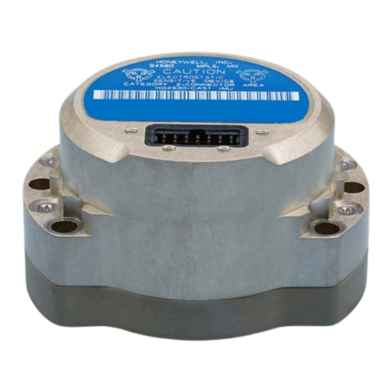
NLR IMU’s will fit your current and future needs. The HG4930 IMU is a device which measures angular rates and linear accelerations in a body mounted strapdown configuration. It will provide compensated incremental angle and velocity data for navigation as wellas angular rates and linear accelerations for control. -
Page 5: Electrical Interface
HG4930 Installation and Interface Manual aerospace.honeywell.com/HG4930 Electrical Interface The pin assignments of the external system connector are shown below. Logic 0 corresponds to the CMOS “low” logic state. Logic 1 corresponds to the CMOS “high” logic state. Table 1. Connector Pin Description... -
Page 6: Asynchronous Protocol
HG4930 Installation and Interface Manual aerospace.honeywell.com/HG4930 Asynchronous Protocol General Description The IMU supports the asynchronous RS-422 compatible protocol. Each Asynchronous output frame will open with an IMU address byte that can be used as a synching byte. The asynchronous 600/100 Hz data protocol is as specified in Table 3 – Control Message (0x01) Format and Table 7 –... -
Page 7: Rotation Correction
HG4930 Installation and Interface Manual aerospace.honeywell.com/HG4930 Rotation Correction The IMU shall subtract the “rotation correction” from the inertial delta-velocity components of message ID 0x02 to allow direct integration of the synchronously sampled body-axis delta-angle and delta-velocity elements. The “rotation correction” consists of one half of the sampled delta-angle vector cross the sampled delta-velocity vector. -
Page 8: Table 3. Asynchronous Control Message (0X01 Format)
HG4930 Installation and Interface Manual aerospace.honeywell.com/HG4930 Table 3. Asynchronous Control Message (0x01 Format) POSITION PARAMETER LENGTH LSB WEIGHT UNITS OR CONTENTS (BYTES) IMU Address Constant 0x0E Message ID Constant 0x01 Angular Rate X * 600 rad/sec/LSB Angular Rate Y * 600... -
Page 9: Table 5. Asynchronous Control Message Field Status Word 2A
HG4930 Installation and Interface Manual aerospace.honeywell.com/HG4930 Table 5. Asynchronous Control Message Field Status Word 2A DEFINITION NOTES Bit 0-7 Software Version Number Bit 8 Gyro Health 0=OK, 1=Failed Bit 9 Start data flag 0=sensor data, 1=0x5555 data transmitted for synchronization... -
Page 10: Normal Operation Mode Description
HG4930 Installation and Interface Manual aerospace.honeywell.com/HG4930 Normal Operation Mode Description The serial data interface is operational within 300 milliseconds after the last applied power form is within the specified tolerances and the reset line is inactive. The IMU transmits a fixed pattern 0x5555 (Hex) in place of Control sensor data and 0x55555555 (Hex) in place of Inertial sensor data until the completion of Power Up BIT. -
Page 11: Mechanical Drawing And Installation
Mechanical Drawing and Installation A CAD compatible STP file is available from Honeywell upon request. The typical IMU weight is 140 grams (0.3 lbs). Figure 5 lists installation notes which should be carefully reviewed. With regards to note 12 regarding SPIRALOCK threads - Honeywell recommends a #2-56 UNC 2B screw (2ea) torqued to 4.25 in-lbs for the I/O connector. - Page 12 HG4930 Installation and Interface Manual aerospace.honeywell.com/HG4930 Figure 5. Installation Drawing...
-
Page 13: Export Guidance
HG4930 Installation and Interface Manual aerospace.honeywell.com/HG4930 Export Guidance All technology that leaves the United States is subject to export regulations. This manual contains technology that has an Export Commodity Classification of ECCN 7E994 with associated country chart control code of AT1. This technology generally will not require a license to be exported or re-exported.
Need help?
Do you have a question about the HG4930 and is the answer not in the manual?
Questions and answers