Table of Contents
Advertisement
Quick Links
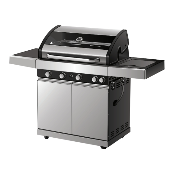
Horizon 4 Burner BBQ
FEATURES
• Deluxe BBQ featuring vitreous enamel
body and stainless steel fascia
• Stainless steel hood includes glass
window and temperature gauge
• Stylish cabinet with stainless
steel doors
Gasmate
®
is a registered trademark of: Sitro Group Australia Pty Ltd www.gasmate.com.au
Important: Retain these instructions for future use.
03245 05/15
BQ8401
• Electronic ignition
• Stainless steel tube burners
• Vitreous enamel cast iron grill and
reversible hotplate
• Operates on Universal L.P.G.
• IAPMO Oceana certified
Aber – Hamilton, N.Z.
www.gasmate.co.nz
Advertisement
Table of Contents

Related Manuals for Gasmate Horizon BQ8401


Summary of Contents for Gasmate Horizon BQ8401
- Page 1 • Stylish cabinet with stainless • Operates on Universal L.P.G. steel doors • IAPMO Oceana certified Gasmate ® is a registered trademark of: Sitro Group Australia Pty Ltd www.gasmate.com.au Aber – Hamilton, N.Z. www.gasmate.co.nz Important: Retain these instructions for future use. 03245 05/15...
-
Page 2: If You Smell Gas
GEnERAl InFoRmATIon Hose & Regulator Safety The regulator and hose assembly supplied with the ImPoRTAnT barbecue are suitable for Propane Gas or Universal L.P.G. only. Read these instruction carefully prior to use. A gas regulator adjusted to have an outlet Familiarise yourself with the appliance before pressure of 2.75kPa is supplied for connection to connecting it to it’s gas container. -
Page 3: Customer Service
IF THERE IS A lEAK FoR YoUR SAFETY • Turn the cylinder off. • Ventilate the area to disperse gas. • Failure to comply with these instructions • Check all connections. could result in a fire or explosion which could cause serious bodily injury, death or •... -
Page 4: General Information
GEnERAl InFoRmATIon location of your Barbecue FoR YoUR SAFETY DO NOT use your barbecue in garages, porches, sheds, breezeways, or other enclosed areas. Your barbecue is to be used OUTDOORS. The barbecue • Do not store or use petrol or other is not intended to be installed in or on recreational flammable liquids in the vicinity of this or vehicles and/or boats and should not be placed... -
Page 5: Care And Maintenance
CARE & mAInTEnAnCE Care of Cooking Surface As with all appliances, proper care and maintenance will keep them in top operating Use and care of the cooking surface is important. condition and prolong their life. Your new gas Do not use pans on the cooking surface. Do not barbecue is no exception. - Page 6 BQ8401 - EXPlodEd dIAGRAm...
- Page 7 BQ8401 - PARTS lIST 1. Hood & Body 2. Warming Rack 3. Flame Tamer 4. Cast Iron Cooking 5. Cast Iron Plate Assembly 2pcs Grill 1pc 6. Side Shelf 7. Side Burner 8. Side Burner Trivet 9. Side Burner 10. Drip Tray Assembly Assembly 11.
- Page 8 ASSEmBlY InSTRUCTIonS Note: Remove any transit protection material. Tools Required: Phillips head screwdriver (or cordless drill and bits) Flat head screwdriver Adjustable spanner STEP 1 Attach the castor wheels (20 & 21) to the base panel (19) using 4 x M6x12 screws per castor. Ensure locking castors (21) are located at the back.
- Page 9 STEP 3 Attach the cabinet back panel (18) between the left and right cabinet side panels using 4 x M6x12 screws. Secure the cabinet back panel to the base panel with 1 x M6x12 screw in the centre. Ensure that the vents in the cabinet back panel are at the top.
- Page 10 STEP 5 Attach 1 x cabinet side top panel (14) to each cabinet side panel using 4 x M5x10 screws. Then secure the cabinet top panel (13) to the cabinet side top panels using 6 x M6x12 screws. Now secure the cabinet top panel (13) to the cabinet back panel using 3 x M6x12 screws. STEP 6 Attach cabinet doors (22, 23) by inserting the bottom hinge pins into the base panel using the holes provided at the front.
- Page 11 STEP 7 With the help of a friend place the body assembly (1) onto the top of the cabinet assembly. Secure with 4 x M6x12 screws and 4 x C washer (28) to the top of the left and right hand cabinet side panels. Attach the hose and regulator assembly ensuring a tight seal is created.
- Page 12 STEP 9.1 Attach the side burner side shelf assembly (7) by loosening the top front and back screws on the left hand side of the body assembly by 5 - 10mm. Then slot the screw heads through the large holes in the side shelf assembly. Push down on the side shelf so that the screw head slots into the top narrow part of the hole.
- Page 13 STEP 9.3 Insert the side burner (9) into the side burner side shelf bowl by positioning the burner tube through hole in shelf. Secure side burner to shelf with 2 x M4 nickel plated screws. Make sure that the side burner engages the side burner valve at the front of the side shelf. Insert side burner trivet (8) over side burner ensuring trivet lines up with the holes in the side shelf bowl.
- Page 14 STEP 11 Insert flame tamers (3) into the body assembly over the 2 burners starting from the left burner. Then add cast iron grill (4) over burners with flame tamers and then cast iron hot plate(5) on the right. Insert warming rack into the holes at either side of the back of the fire bx and rest front bars in rotisserie hoops.
-
Page 15: Bbq Specifications
STEP 12 Open the cabinet door, and let the hose go through the cabinet side panel to connect to the cylinder. Open the cylinder valve and leak test all connections with a soapy water solution. BBQ SPECIFICATIonS overall Barbecue dimensions - Including Side Shelves Barbecue Hood Model... -
Page 16: General Assembly
GEnERAl ASSEmBlY Connecting & disconnecting to Gas lIGHTInG PRoCEdURE Source Burner operation & Ignition System Familiarise yourself with the general information Check and safety guidelines located at the front of this 1. With cylinder valve in ‘OFF’ position push and manual. -
Page 17: Operation
oPERATIon Burner operation & Ignition System Check Problem Possible Reason Solution Valve on gas bottle closed Open valve on gas bottle Control knob is closed Turn knob to high when lighting Burner will not ignite Igniter is faulty Use a long barbecue match. Insert through the hole at side of barbecue Burner has gone out Check that the gas bottle is not empty... -
Page 18: Safe Appliance Locations
SAFE APPlIAnCE loCATIonS This appliance shall only be used in an above ground open-air situation with natural ventilation, without stagnant areas, where gas leakage and products of combustion are rapidly dispersed by wind and natural convection. Any enclosure in which the appliance is used shall comply with the following: An enclosure with walls on all sides, but at least one permanent opening at ground level and no overhead cover.
Need help?
Do you have a question about the Horizon BQ8401 and is the answer not in the manual?
Questions and answers