Table of Contents
Advertisement
Quick Links
Download this manual
See also:
Operating Manual
Advertisement
Table of Contents

Related Manuals for Bosch VJC-7000-90


Summary of Contents for Bosch VJC-7000-90
- Page 1 Videojet connect 7000 VJC‑7000‑90 Installation Manual...
-
Page 3: Table Of Contents
Control of Connected Devices System Requirements Configuration Overview About the SETTINGS Page General settings Identification 7.1.1 Naming 7.1.2 7.1.3 iSCSI Initiator extension Password Date/Time Web Interface Appearance LIVE Functions Logging Bosch Security Systems Installation Manual 2019-08 | 1.7 | F.01U.291.524... - Page 4 Authentication (802.1x) 12.4 Network Management 12.4.1 SNMP 12.4.2 UPnP 12.4.3 Quality of Service 12.5 Switch Configuration 12.6 Accounts 12.7 IPv4 Filter 12.8 Encryption Service 13.1 Installer Menu 13.2 Maintenance 13.3 Licenses 2019-08 | 1.7 | F.01U.291.524 Installation Manual Bosch Security Systems...
- Page 5 Configure VIDEOJET connect 7000 to Operate with a MIC7000 Camera 15.1 Configure Alarm Inputs and Outputs 15.2 Configure Audio 15.3 Configure Video Playback Troubleshooting and Maintenance 16.1 Troubleshooting 16.2 Maintenance Technical data Bosch Security Systems Installation Manual 2019-08 | 1.7 | F.01U.291.524...
-
Page 6: Safety
Legal Information Copyright This manual is the intellectual property of Bosch Security Systems, Inc. and is protected by copyright. All rights reserved. Trademarks All hardware and software product names used in this document are likely to be registered trademarks and must be treated accordingly. -
Page 7: Important Safety Instructions
Power disconnect - An appropriate disconnect device shall be provided external to the equipment. Surge suppression - Use proper surge suppression on your network video, power, audio, and alarm cables. Bosch Security Systems Installation Manual 2019-08 | 1.7 | F.01U.291.524... -
Page 8: Important Notices
Any such modifications could void the user's authority to operate the equipment. If necessary, the user should consult the dealer or an experienced radio/television technician for corrective action. 2019-08 | 1.7 | F.01U.291.524 Installation Manual Bosch Security Systems... -
Page 9: Customer Support And Service
Videojet connect 7000 Safety | en Customer Support and Service If this unit needs service, contact the nearest Bosch Security Systems Service Center for authorization to return and shipping instructions. Service Centers Telephone: 800-366-2283 or 585-340-4162 Fax: 800-366-1329 Email: cctv.repair@us.bosch.com... -
Page 10: Unpacking
Verify that all the parts listed in the Parts List below are included. If any items are missing, notify your Bosch Security Systems Sales or Customer Service Representative. – Do not use this product if any component appears to be damaged. Please contact Bosch Security Systems in the event of damaged goods. –... -
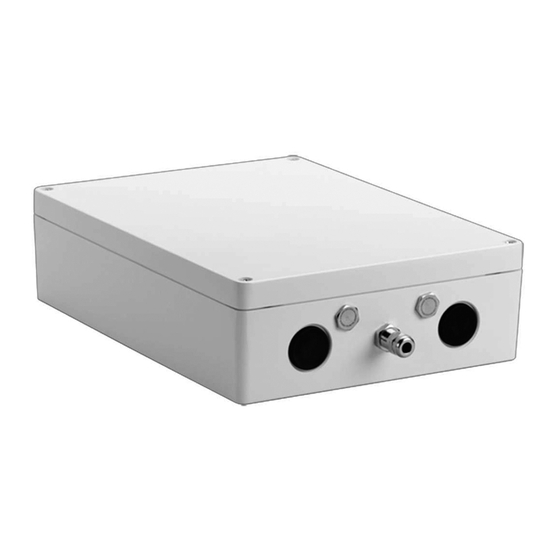
Page 11: Product Overview
The device VIDEOJET connect 7000 (VJC-7000-90) is a full-featured network power supply unit that can operate a variety of Bosch PTZ cameras such as MIC7000. The device includes one (1) HPoE network connection, two (2) standard network interfaces for connections to... -
Page 12: Typical Configuration - Basic
VIDEOJET connect 7000 device. Note: To achieve a distance of 100 m (328 ft) using Cat5e/Cat6e cable, Bosch recommends using cable with a minimum rating of 350 MHz. -
Page 13: Typical Configuration - Daisy Chain
Cat5e/Cat6e = 100 m max. Figure 3.2: Typical daisy chain configuration for VIDEOJET connect 7000 Ethernet (network) cable (Cat5e/Cat6e) (user-supplied) between a Bosch camera and the port labeled PoE on VIDEOJET connect 7000 Data-only IP cable (Cat5e/Cat6e) to the head-end network Note: The cable to the head-end also can be fiber optic cable from one of the two SFP slots. -
Page 14: Typical Configuration - Multiple Cameras To Head-End Network
1 Ethernet (network) cable (Cat5e/Cat6e) (user-supplied) between a Bosch camera and the port labeled PoE on VIDEOJET connect 7000 2 Data-only IP cable (Cat5e/Cat6e) between a Bosch IP camera and the port labeled ETH 2 on VIDEOJET connect 7000 3 Head-end network... -
Page 15: Typical Configuration - Mobile Viewing
Typical Configuration - Mobile Viewing Cat5e/Cat6e = 100 m max. Figure 3.4: Mobile Viewing using the integrated Transcoder of VIDEOJET connect 7000 1 Ethernet (network) cable (Cat5e/Cat6e) (user-supplied) between a Bosch camera and the port labeled PoE on VIDEOJET connect 7000 2 Network switch (user-supplied) 3 Head-end network 4 Internet (“the cloud”) -
Page 16: Technical Data
If a MIC7000 camera is assigned to Camera 1 in the Transcoder Setup, it becomes “bound” to the alarm inputs/outputs, the audio input/output, and the washer output provided by the VIDEOJET connect 7000 device. 2019-08 | 1.7 | F.01U.291.524 Installation Manual Bosch Security Systems... -
Page 17: Dimensional Drawing
Videojet connect 7000 Technical Data | en Dimensional Drawing Bosch Security Systems Installation Manual 2019-08 | 1.7 | F.01U.291.524... -
Page 18: Installation
Electrical Code ® (NEC)), Canadian Electrical Code, Part I (also called CE Code or CSA C22.1), and all applicable local codes. Bosch Security Systems accepts no liability for any damages or losses caused by incorrect or improper installation. Warning! Overvoltage hazard This product requires a surge protector device (SPD) or surge arrester as part of the installation to address overvoltages exceeding Overvoltage Category II, 2500 Vpk. -
Page 19: Mounting
If you are securing the enclosure in a vertical position (for example, on a wall), one person should hold the enclosure lid while another person secures the enclosure body in place, to avoid damage to any part of the enclosure, and/or injury to the installers. Bosch Security Systems Installation Manual 2019-08 | 1.7 | F.01U.291.524... -
Page 20: Conduit Installation
Secure the conduit as recommended by the conduit manufacturer. Note: Use the figure of the layout of the Printed Circuit Board Assembly (PCBA) on the next page as reference when completing steps 5 – 13. 2019-08 | 1.7 | F.01U.291.524 Installation Manual Bosch Security Systems... -
Page 21: Pcba Connections
Two (2) slots for use with SFP-based fiber optic modules (1 GB only) (user-supplied) Two (2) RJ45 Ethernet (female) ports (labeled ETH1, ETH2) One (1) RJ45 HPoE Ethernet (female) port (labeled PoE) Ground lug, AC mains (required) Bosch Security Systems Installation Manual 2019-08 | 1.7 | F.01U.291.524... -
Page 22: Power Cable Installation
– Terminate the cable. – Connect the cable to the appropriate SFP socket(s). Alarm Inputs * Note: This feature is valid only for a MIC7000 camera "bound" to Camera 1. 2019-08 | 1.7 | F.01U.291.524 Installation Manual Bosch Security Systems... -
Page 23: Alarm Outputs
PCBA (item 2). – Make the connections to the connector according to the table below. Description / Function Relay Normally Open Relay Common – Check that the connections are secure. Bosch Security Systems Installation Manual 2019-08 | 1.7 | F.01U.291.524... -
Page 24: Audio In And Out
13. Install a CF card to save recordings locally, if applicable. Caution! Bosch recommends disconnecting power to the unit whenever inserting or removing a CF card. Carefully slide a Type I / Type II, True IDE Mode, 1 TB max CF card into the card slot (item 9) as far as it will go until it locks into place. -
Page 25: Control Of Connected Devices
You can find notes on using Microsoft Internet Explorer in the online Help in Internet Explorer. If you choose to use a computer running Microsoft Internet Explorer or any of the Bosch software, the computer must conform to the following minimum requirements: –... -
Page 26: Configuration Overview
Some changes only take effect after the unit is rebooted. In this case, the Set button changes to Set and Reboot. Make the desired changes. Click the Set and Reboot button. The camera reboots and the changed settings are activated. 2019-08 | 1.7 | F.01U.291.524 Installation Manual Bosch Security Systems... -
Page 27: General Settings
You can define and change a password for each authorization level if you are logged in as service or if the unit is not password protected. Enter the password for the appropriate authorization level here. Bosch Security Systems Installation Manual 2019-08 | 1.7 | F.01U.291.524... -
Page 28: Date/Time
Make changes by clicking an entry in the table. The entry is selected. Clicking the Delete button will remove the entry from the table. Select other values from the list fields below the table to change the entry. Changes are made immediately. 2019-08 | 1.7 | F.01U.291.524 Installation Manual Bosch Security Systems... - Page 29 SNTP server as the protocol. This supports a high level of accuracy and is required for special applications and subsequent function extensions. Select Time server for a time server that works with the protocol RFC 868. Bosch Security Systems Installation Manual 2019-08 | 1.7 | F.01U.291.524...
-
Page 30: Web Interface
Video player Select the desired video player from the list in the drop-down box. Options are “Auto detect” (default), Bosch Video SDK, Bosch Autoload Decoder, JPEG JPEG size You can specify the size of the JPEG image on the LIVE page. Options are Small, Medium, Large, 720p, 1080p, and “Best possible”... -
Page 31: Live Functions
Office software. File for system log Enter the path for saving the system log here. If necessary, click Browse to find a suitable directory. Bosch Security Systems Installation Manual 2019-08 | 1.7 | F.01U.291.524... -
Page 32: Transcoder
If your router has UPnP enabled, click Configure Router to save the settings to the router. Otherwise, configure your router manually. The cameras are now available for selection on the PLAYBACK page. Transcoding will only be possible once recordings for the cameras are available. 2019-08 | 1.7 | F.01U.291.524 Installation Manual Bosch Security Systems... -
Page 33: Transcoder Profile
The image rate in (images per second (ips) appears next to the text field or slider. Bosch Security Systems Installation Manual 2019-08 | 1.7 | F.01U.291.524... -
Page 34: Base Resolution
9.2.8 Deblocking filter Deblocking filter You can activate a filter that reduces blocking in the image, thereby providing a smoother image. Please note that this option requires additional computing power. 2019-08 | 1.7 | F.01U.291.524 Installation Manual Bosch Security Systems... -
Page 35: Cabac
Note: The current GUI shows 2 Line Inputs, but only 1 is supported. Note: Audio OUT is not available in initial production units. A firmware update, expected in mid-2015, is required. Bosch Security Systems Installation Manual 2019-08 | 1.7 | F.01U.291.524... -
Page 36: Recording
It is also possible to let the VRM Video Recording Manager control all recordings when accessing an iSCSI system. This is an external program for configuring recording tasks for video servers. For further information please contact your local customer service at Bosch Security Systems. -
Page 37: Remote Video Device
This page provides information on the current recording status of the cameras connected to VIDEOJET connect 7000. For easy identification, the IP address of the connected camera is the heading for each corresponding information block. Bosch Security Systems Installation Manual 2019-08 | 1.7 | F.01U.291.524... -
Page 38: Status
Click Set to save the settings. The recording target is the one defined in the transcoder. Only recordings to this target will now be available on the PLAYBACK page. 10.3.6 Start/Stop Recording Click the respective button to start or stop the recording for a camera. 2019-08 | 1.7 | F.01U.291.524 Installation Manual Bosch Security Systems... -
Page 39: Alarm
When you are finished, click the Set button to transmit the scripts to the unit. If the transfer was successful, the message Script successfully parsed is displayed over the text field. If it was not successful, an error message will be displayed with further information. Bosch Security Systems Installation Manual 2019-08 | 1.7 | F.01U.291.524... -
Page 40: Network
If a DHCP server is employed in the network for the dynamic assignment of IP addresses, you can activate acceptance of IP addresses automatically assigned to the camera. Certain applications (Bosch Video Management System, Archive Player, Configuration Manager) use the IP address for the unique assignment of the unit. If you use these... - Page 41 Telnet protocol. Interface mode ETH If necessary, select the Ethernet link type for the ETH interface. Depending on the unit connected, it may be necessary to select a special operation type. Bosch Security Systems Installation Manual 2019-08 | 1.7 | F.01U.291.524...
-
Page 42: Dyndns
IP address of the unit. You can enable this service here. To do this, you must have an account with DynDNS.org and you must have registered the required host name for the unit on that site. 2019-08 | 1.7 | F.01U.291.524 Installation Manual Bosch Security Systems... -
Page 43: Advanced
12.3 Advanced 12.3.1 Cloud-based Services The operation mode determines how the camera communicates with Bosch Cloud-based Security and Services. For more information about these services and their availability, visit: http://cloud.boschsecurity.com – Select Auto to allow the camera to poll the server a few times; if no contact is made, it stops polling. -
Page 44: Upnp
PAUSE frame in order to clear the existing buffers. By default, flow control is enabled. Bosch recommends to use it for the daisy chain configuration, but to disable it if the VIDEOJET connect 7000 unit is connected as a single unit. -
Page 45: Ipv4 Filter
The device itself may initiate a connection (for example, to send an alarm) outside the defined ranges if it is configured to do so. 12.8 Encryption If an encryption license is installed, this submenu gives access to the encryption parameters. Bosch Security Systems Installation Manual 2019-08 | 1.7 | F.01U.291.524... -
Page 46: Service
Make certain that the file to be loaded comes from the same unit type as the unit you want to configure. Next, click Upload to begin transferring the file to the unit. The progress bar allows you to monitor the transfer. 2019-08 | 1.7 | F.01U.291.524 Installation Manual Bosch Security Systems... -
Page 47: Licenses
You can select all required text on this page with the mouse and copy it to the clipboard with the [Ctrl]+[C] key combination, for example if you want to send it via e-mail. Bosch Security Systems Installation Manual 2019-08 | 1.7 | F.01U.291.524... -
Page 48: Operation Via The Browser
When accessing the unit with a browser, the local storage, processor and network status icons are shown in the upper right of the window next to the Bosch logo. When a local storage card is available, the memory card icon changes color (green, orange or red) to indicate the local storage activity. -
Page 49: Status Icons
(With VRM recording this option is not active.) A collapsible panel on the left of the display has four tabs: – Track list – Export Bosch Security Systems Installation Manual 2019-08 | 1.7 | F.01U.291.524... -
Page 50: Selecting Recordings For Playback
– If required, click in the bar at the point in time at which the playback should begin. – Red bars indicate the points in time where alarms were triggered. 2019-08 | 1.7 | F.01U.291.524 Installation Manual Bosch Security Systems... - Page 51 Jump to the following bookmark Bookmarks are only valid while in the Recordings page; they are not saved with the sequences. All bookmarks are deleted when you leave the page. Bosch Security Systems Installation Manual 2019-08 | 1.7 | F.01U.291.524...
-
Page 52: Configure Videojet Connect 7000 To Operate With A Mic7000 Camera
Counter) appears only in the configuration menu of the camera “bound” to VIDEOJET connect 7000. 15.3 Configure Video Playback To configure video playback with VIDEOJET connect 7000, first you must map the device to record. See Recording for details. 2019-08 | 1.7 | F.01U.291.524 Installation Manual Bosch Security Systems... -
Page 53: Troubleshooting And Maintenance
- the device does not operate normally when the user follows the operating instructions correctly. Servicing - Do not attempt to service this device yourself. Refer all servicing to qualified service personnel. Bosch Security Systems Installation Manual 2019-08 | 1.7 | F.01U.291.524... -
Page 54: Technical Data
| Technical data Videojet connect 7000 Technical data For more specific product details, see the VIDEOJET connect 7000 datasheet. 2019-08 | 1.7 | F.01U.291.524 Installation Manual Bosch Security Systems... - Page 55 Videojet connect 7000 Technical data | Bosch Security Systems Installation Manual 2019-08 | 1.7 | F.01U.291.524...
- Page 56 | Technical data Videojet connect 7000 2019-08 | 1.7 | F.01U.291.524 Installation Manual Bosch Security Systems...
- Page 58 Bosch Sicherheitssysteme GmbH Bosch Security Systems, Inc Robert-Bosch-Ring 5 1706 Hempstead Road 85630 Grasbrunn Lancaster, PA, 17601 Germany www.boschsecurity.com © Bosch Sicherheitssysteme GmbH, 2019...
Need help?
Do you have a question about the VJC-7000-90 and is the answer not in the manual?
Questions and answers