
Subscribe to Our Youtube Channel
Related Manuals for Creative Play Pirate Ship Midi


Summary of Contents for Creative Play Pirate Ship Midi
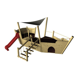
- Page 1 PIRATE SHIP Installation Instructions REF: VOY118 - PIRATE SHIP MIDI (TIMBER) pg 1 of 49...
-
Page 2: Table Of Contents
SECTION 1 - Main Assembly pg. 18-30 SECTION 2 - Additional Parts pg. 31-47 Triangular Sail Shade pg. 42-43 1.0m Slide pg. 47 Additional Additional Drawings pg. 48-49 Notes pg. 49 REF: VOY118 - PIRATE SHIP MIDI (TIMBER) pg 2 of 49... -
Page 3: Full Round Timbers
VOY118i - QTY - 1 150mm dia @ 3804mm (1 holes / chamfer 1 end) VOY118j - QTY - 1 150mm dia @ 2580mm (2 holes / chamfer 1 end) REF: VOY118 - PIRATE SHIP MIDI (TIMBER) pg 3 of 49... -
Page 4: Main Panels
PARTS required continued MAIN PANELS - STARBOARD SIDE (right) MAIN PANELS - PORT SIDE (left) REF: VOY118 - PIRATE SHIP MIDI (TIMBER) pg 4 of 49... -
Page 5: Floor Supports
PARTS required continued MAIN PANELS - ADDITIONAL (internal) ASSEMBLY ASSEMBLY FLOOR SUPPORTS REF: VOY118 - PIRATE SHIP MIDI (TIMBER) pg 5 of 49... -
Page 6: Other Parts / Assemblies
Consists of... 2 x HANDRAILS 5 x Pre-assembled ‘STEPS’ inc ropes 1 x Attachment timber 2 x WBR2 ROPES NET CLIMBER CARGO NET (metal support / ground anchour supplied separately) REF: VOY118 - PIRATE SHIP MIDI (TIMBER) pg 6 of 49... - Page 7 (M12 Nylocs) (BOW SHACKLE) 1.0m SLIDE CLIMBING BLOCKS QTY - 16 (backs) QTY - 16 (fronts) (2 x metal ground anchors / 1 x platform support / fixings included) REF: VOY118 - PIRATE SHIP MIDI (TIMBER) pg 7 of 49...
-
Page 8: Hex Board
PARTS required continued AR - Additional Ropes (Nets) HEX BOARD - ‘UPPER DECK’ STERN TRIM PIECE HEX BOARD - ‘LOWER DECK’ REF: VOY118 - PIRATE SHIP MIDI (TIMBER) pg 8 of 49... -
Page 9: Fixings Required
SCREW - 34 required) (7.5x40 MULTIFIX SCREW - 72 required) (‘NYLOCS’ M12 - Nylon locking nuts - 46 required) (6x80 RAPID DRIVE SCREW) fixings for NET HOLDERS TOOLS required REF: VOY118 - PIRATE SHIP MIDI (TIMBER) pg 9 of 49... -
Page 10: Surfacing Details
SURFACING Details OVERALL AREA = MINIMUM SPACE = SURFACE AREA NOTES: The slide ‘OUTLINE’ has been included to help highlight the orientation of the area REF: VOY118 - PIRATE SHIP MIDI (TIMBER) pg 10 of 49... - Page 11 SURFACING Details OVERALL AREA - DATUM LINE DATUM LINE VOY118 VOY118 VOY118 VOY118 CREATE A DATUM LINE Using the 1 x 150mm & 1 X 200mm‘MAIN UPRIGHT’ posts REF: VOY118 - PIRATE SHIP MIDI (TIMBER) pg 11 of 49...
-
Page 12: Foundation Details
The slide ‘OUTLINE’ has been included to help highlight the orientation of the area 4) DIRECTION OF HOLES Ensure the PRE DRILLED HOLES are positioned as shown - Dashed lines show holes going in the opposite direction REF: VOY118 - PIRATE SHIP MIDI (TIMBER) pg 12 of 49... - Page 13 FOUNDATION Details FULL ROUND POSTS VOY118 VOY118 VOY118 VOY118 VOY118 VOY118 VOY118 VOY118 VOY118 VOY118 VOY118 VOY118 VOY118 VOY118 VOY118 SIDE VIEW REF: VOY118 - PIRATE SHIP MIDI (TIMBER) pg 13 of 49...
- Page 14 FOUNDATION Details WOBBLY BRIDGE POSTS VOY118 VOY118 SIDE VIEW VOY118 VOY118 REF: VOY118 - PIRATE SHIP MIDI (TIMBER) pg 14 of 49...
- Page 15 FOUNDATION Details NET CLIMBER NOTES: The NET GROUND ANCHOUR needs to sit 5-10mm below FINISHED GROUND LEVEL SIDE VIEW REF: VOY118 - PIRATE SHIP MIDI (TIMBER) pg 15 of 49...
- Page 16 The bottom section of the SLIDE will need to be installed INTO THE GROUND HOLE = 600mm x 600mm x 600mm (ensure concrete is laid 150mm below finished ground level) SIDE VIEW REF: VOY118 - PIRATE SHIP MIDI (TIMBER) pg 16 of 49...
-
Page 17: Installation Notes
4) The floors for the main deck / bow / stern are NOT drilled - When attaching the HEX BOARD to the floor support timbers COUNTERSINK and ensure they are kept uniform (where possible) - GENERAL 5) The majority of the instructions are orientated showing the looking toward the BOW from the STERN STARBOARD SIDE REF: VOY118 - PIRATE SHIP MIDI (TIMBER) pg 17 of 49... -
Page 18: Section 1 - Main Assembly
GROUND LEVEL is essential as the 18mm HEX board floors will sit on top of the 90x90 support timber - MUST SIT @ a finished height of 1000mm MPA11 MPA10 FACING TOWARDS BOW REF: VOY118 - PIRATE SHIP MIDI (TIMBER) pg 18 of 49... - Page 19 GROUND LEVEL is essential as the 18mm HEX board floors will sit on top of the 90x90 support timber - MUST SIT @ a finished height of 447mm MPA9 FACING TOWARDS BOW REF: VOY118 - PIRATE SHIP MIDI (TIMBER) pg 19 of 49...
- Page 20 Installation Instructions Attach the MAIN PANELS to main posts MPP7 MPS3 Attach MAIN PANELS MAIN POSTS - using 16 FM80 SCREWS MPP7 MPS3 MPP7 REF: VOY118 - PIRATE SHIP MIDI (TIMBER) pg 20 of 49...
- Page 21 Attach MAIN PANELS MAIN POSTS - using 16 FM180 SCREWS MPP6 MPS2 NOTES: FM180’s required as the screws will need to go through 90x90 timbers and the support timber REF: VOY118 - PIRATE SHIP MIDI (TIMBER) pg 21 of 49...
- Page 22 8 x FM180 WOOD SCREWS NOTES: FSL - Floor Support Lower FSL12 Attach the FLOOR SUPPORTS to main panels FSU3 FSU4 Attach FLOOR SUPPORTS using 4 x FM180 WOOD SCREWS FSU3 FSU4 REF: VOY118 - PIRATE SHIP MIDI (TIMBER) pg 22 of 49...
- Page 23 BOW and STERN assemblies are reliant on the angles of the MAIN DECK being correct Attach the MAIN PANEL to main posts MPP5 Attach MAIN PANELS MAIN POSTS - using 12 FM80 SCREWS REF: VOY118 - PIRATE SHIP MIDI (TIMBER) pg 23 of 49...
- Page 24 TRIMMED to ensure a TIGHT FIT see FIG 4 FIG.4 Attach the FLOOR SUPPORTS to main panels FSL11 FSL10 FSL8 Attach FLOOR SUPPORTS to using 12 x FM80 SCREWS REF: VOY118 - PIRATE SHIP MIDI (TIMBER) pg 24 of 49...
- Page 25 Attach FLOOR SUPPORTS x 2 using 6 x FM80 SCREWS FSL9 NOTES: The FSL9 timbers will sit in the NOTCHED OUT SECTIONS of the FSL11 / FSL10 / FSL8 REF: VOY118 - PIRATE SHIP MIDI (TIMBER) pg 25 of 49...
- Page 26 Attach the FLOOR SUPPORTS to the floor FSU1 FSU2 Attach FLOOR SUPPORTS using 8x FM180 SCREWS Attach the MAIN PANEL to main posts MPP8 Attach MAIN PANELS MAIN POSTS - using 14 FM80 SCREWS MPP8 REF: VOY118 - PIRATE SHIP MIDI (TIMBER) pg 26 of 49...
- Page 27 Screw through the 45mm x 45mm support into the ROUND TIMBERS (SEE FIG. 1) Attach the MAIN PANEL to main posts MPS4 Attach MAIN PANELS MAIN POSTS - using 14 FM80 SCREWS REF: VOY118 - PIRATE SHIP MIDI (TIMBER) pg 27 of 49...
- Page 28 Installation Instructions Attach the MAIN PANEL to main posts MPA12 Attach MAIN PANELS MAIN POSTS - using 14 FM80 SCREWS MPA12 REF: VOY118 - PIRATE SHIP MIDI (TIMBER) pg 28 of 49...
- Page 29 Instructions for the main assembly BOW / MAIN DECK / STERN have been completed. The remainder of the instructions are for additional assemblies / ropes & nets / slide / hex board / sails REF: VOY118 - PIRATE SHIP MIDI (TIMBER) pg 29 of 49...
- Page 30 Installation Instructions SECTION VIEW of the MAIN ASSEMBLY Check dimensions as shown below SECTION VIEW A-A REF: VOY118 - PIRATE SHIP MIDI (TIMBER) pg 30 of 49...
-
Page 31: Section 2 - Additional Parts
Using 26 x M12 NYLOCS / 13 END CAPS FSU4 NOTES: END CAPS are only required into the FSU4 timber - no access to the LOWER ROPES circled RIGHT REF: VOY118 - PIRATE SHIP MIDI (TIMBER) pg 31 of 49... - Page 32 Using 4 x M12 NYLOCS / 4 END CAPS Attach the TIMBER Use 2 x M12x215 CUP SQUARE BOLTS / NYLOCS / END CAPS to attach the rope timber to the A-C timbers (SHOWN ABOVE) REF: VOY118 - PIRATE SHIP MIDI (TIMBER) pg 32 of 49...
- Page 33 Attach the WOBBLY BRIDGE hand rails Using 8 x FM80 WOOD SCREWS ENSURE The timber is positioned the CORRECT WAY - Larger angle cut is the lower END (see below) REF: VOY118 - PIRATE SHIP MIDI (TIMBER) pg 33 of 49...
- Page 34 ENSURE: Gaps are as shown BLACK - this is to ensure no entrapment is present Attach the WOBBLY BRIDGE assemblies together Using 20 x POLYFIX HALF (4 per SLAT) REF: VOY118 - PIRATE SHIP MIDI (TIMBER) pg 34 of 49...
- Page 35 1) Position all the floors in each section (eg the MAIN DECK) before SCREWING INTO POSITION 2) ENSURE ALL HOLES ARE PRE-DRILLED and COUNTERSUNK Position and Attach the LOWER - HEX BOARD FLOORS Position Position REF: VOY118 - PIRATE SHIP MIDI (TIMBER) pg 35 of 49...
- Page 36 Installation Instructions Position Position Position REF: VOY118 - PIRATE SHIP MIDI (TIMBER) pg 36 of 49...
- Page 37 Installation Instructions Position and Attach the UPPER - HEX BOARD FLOORS Position Position REF: VOY118 - PIRATE SHIP MIDI (TIMBER) pg 37 of 49...
- Page 38 Installation Instructions Position STERN TRIM PIECE Position REF: VOY118 - PIRATE SHIP MIDI (TIMBER) pg 38 of 49...
- Page 39 Installation Instructions Position FSU7 FSU7 NOTES: Screw the FSU7 timbers to the HEX BOARD using 8 x 7.5 x 40 MULTIFIX SCREWS REF: VOY118 - PIRATE SHIP MIDI (TIMBER) pg 39 of 49...
- Page 40 16 x 7.5 x 40 MULTIFIX SCREWS (per floor) 8 x 7.5 x 40 MULTIFIX SCREWS (per floor) HEX BOARD - ‘UPPER DECK’ 16 x FM80 WOOD SCREW (per floor) REF: VOY118 - PIRATE SHIP MIDI (TIMBER) pg 40 of 49...
- Page 41 Installation Instructions Attach Additional Net / Rope AR4 Using 4 x NYLOCS / 2 x END CAPS / 2 x COVERED END CAP R60 REF: VOY118 - PIRATE SHIP MIDI (TIMBER) pg 41 of 49...
-
Page 42: Triangular Sail Shade
Attach the following - BOW SHACKLE to eyebolt / RIGGING SCREW to bow shackle / SHADE SAIL FIXING POINT to rigging screw (RIGGING SCREW) (BOW SHACKLE) POST / UPRIGHT with EYEBOLT ATTACHED (BOW SHACKLE) (RIGGING SCREW) SHADE SAIL FIXING POINT (Part of the shade sail fabric) REF: VOY118 - PIRATE SHIP MIDI (TIMBER) pg 42 of 49... - Page 43 With each point attached to the EYEBOLTS move from point to point TIGHTENING each RIGGING SCREW NOTE: Work your way round TIGHTENING EACH POINT. Each rigging screw should be tightened EQUALLY REF: VOY118 - PIRATE SHIP MIDI (TIMBER) pg 43 of 49...
- Page 44 Attach Additional Net / Rope AR3 Using 2x NYLOCS / 2 x COVERED END CAP R60 Attach Additional Net / Rope AR2 Using 2x NYLOCS / 2 x COVERED END CAP R60 REF: VOY118 - PIRATE SHIP MIDI (TIMBER) pg 44 of 49...
- Page 45 Attach Additional Net / Rope AR1 x 2 Using 8 x 6 x 80 RAPID DRIVE SCREWS NOTES: Dimensions shown below are from HEX BOARD FLOOR to CENTRE of NET HOLDER FIXINGS REF: VOY118 - PIRATE SHIP MIDI (TIMBER) pg 45 of 49...
- Page 46 NOTES: Each CLIMBING BLOCK consists of a FRONT & BACK, position as shown BELOW and screw through the COUNTERSUNK piece (front) through the BACK and into the MAIN PANEL REF: VOY118 - PIRATE SHIP MIDI (TIMBER) pg 46 of 49...
-
Page 47: Slide
Attach the PLATFORM ATTACHMENT using supplied bolts Attach the GROUND ANCHORS using supplied bolts ENSURE middle holes is CENTRED ENSURE: The distance between the FIXING PLATE and EDGE OF HEX FLOOR is 39mm (below) REF: VOY118 - PIRATE SHIP MIDI (TIMBER) pg 47 of 49... -
Page 48: Additional Drawings
Addition Drawings SIDE VIEW FRONT VIEW REF: VOY118 - PIRATE SHIP MIDI (TIMBER) pg 48 of 49... -
Page 49: Notes
Addition Drawings PLAN VIEW SITE NOTES: REF: VOY118 - PIRATE SHIP MIDI (TIMBER) pg 49 of 49...
Need help?
Do you have a question about the Pirate Ship Midi and is the answer not in the manual?
Questions and answers