Asco 8316 Series Installation & Maintenance Instructions Manual
3-way internal or external piloted solenoid valves. 8316. normally closed operation air or inert gas service. 1/4, 3/8 or 1/2 npt - 5/16 or 5/8 orifice
Hide thumbs
Also See for 8316 Series:
- Operating manual (7 pages) ,
- Installation & maintenance instructions (4 pages)
Advertisement
Installation & Maintenance Instructions
3-WAY INTERNAL OR EXTERNAL PILOTED SOLENOID VALVES
NORMALLY CLOSED OPERATION
1/4I, 3/8I OR 1/2I NPT
NOTICE: See separate solenoid installation and maintenance
instructions
for
information
Temperature, Causes of Improper Operation, and Solenoid
Replacement.
For exploded views, see Form No. V6928R3 - Section 2 of 2.
DESCRIPTION
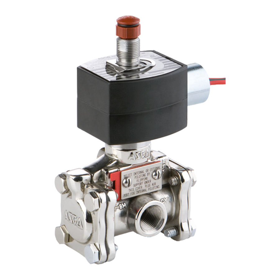
Series 8316 valves are 3-way solenoid valves designed for air
or inert gas service. Depending upon requirements, this valve
may be used in either the Internal Piloting Mode or External
Piloting Mode of operation. This unique valve design allows
the user to relocate (turn over) the Support with Flow Gaskets
to change the mode of valve operation.
information on valve operation, see sections on OPERATION
and CHANGING MODE OF OPERATION.
Series 8316 valves are available in three solenoid versions;
standard, low power and intrinsically safe. Valves are rugged
forged brass with internal parts of stainless steel and low
temperature Buna N elastomers.
NOTICE
This valve is supplied from the factory in the Internal
Piloting Mode of operation. Refer to OPERATION -
INTERNAL PILOTING MODE following.
To change valve mode of operation to External
Piloting Mode, see section on CHANGING MODE
OF OPERATION on page 2 of 6.
OPERATION - INTERNAL PILOTING MODE
IMPORTANT: Internal piloted valves require a minimum
operating pressure differential of 15 psi.
Normally Closed
Solenoid De-energized: Flow is from cylinder CYL " to main
exhaust EXH". Internal pressure is vented briefly through
pilot exhaust. Pressure PRESS" is closed.
Solenoid Energized:
Flow is from pressure PRESS" to
cylinder CYL ". Main exhaust EXH" and pilot exhaust are
closed.
Flow Diagrams
Solenoid De-Energized
PILOT EXH
(main)
EXH
CYL
PRESS
50 Hanover Road, Florham Park, New Jersey 07932 www.ascovalve.com
AIR OR INERT GAS SERVICE
5/16I OR 5/8I ORIFICE
on:
Wiring,
Solenoid
For additional
Solenoid Energized
PILOT EXH
(main)
EXH
CYL
PRESS
MMIII
All Rights Reserved.
OPERATION - EXTERNAL PILOTING MODE
The external piloting mode of operation allows a zero
minimum main line pressure with the application of proper
auxiliary air pressure. Refer to operating instructions (to
follow) and the graph Auxiliary Pilot Pressure vs Main Line
Pressure. Use this graph to determine the minimum auxiliary
air pressure required for a given main line pressure.
Normally Closed
Solenoid De-energized with Auxiliary Pressure Applied: Flow
is from cylinder CYL " to main exhaust EXH". Internal
pressure is vented briefly through pilot exhaust.
PRESS" is closed.
Solenoid Energized with Auxiliary Pressure Applied: Flow is
from pressure PRESS" to cylinder CYL ". Main exhaust
EXH" and pilot exhaust are closed.
Flow Diagrams
Solenoid De-Energized
with Auxiliary Pressure
Applied
PILOT EXH
AUX
(main)
EXH
CYL
PRESS
Note: If main line pressure is lost, with solenoid de-energized
or energized external piloted valves will not change position as
long as auxiliary pilot pressure is present. If auxiliary pilot
pressure is lost while main line pressure is present, valve will
change position if solenoid is energized, but will not change
position if solenoid is de-energized.
Auxiliary Pilot Pressure vs Main Line Pressure
120
105
90
75
60
45
30
15
0
0
15 30 45
60 75 90 105 120 135 150
Main Line Pressure PSI
Page 1 of 8 (Section 1 of 2)
Printed in U.S.A.
SERIES
8316
Form No.V6928R3 - Sec. 1
(Section 1 of 2)
Pressure
Solenoid Energized
with Auxiliary Pressure
Applied
PILOT EXH
AUX
(main)
EXH
CYL
PRESS
Advertisement
Table of Contents

Related Manuals for Asco 8316 Series


Summary of Contents for Asco 8316 Series
- Page 1 Installation & Maintenance Instructions SERIES 8316 3-WAY INTERNAL OR EXTERNAL PILOTED SOLENOID VALVES NORMALLY CLOSED OPERATION AIR OR INERT GAS SERVICE Form No.V6928R3 - Sec. 1 1/4I, 3/8I OR 1/2I NPT 5/16I OR 5/8I ORIFICE (Section 1 of 2) OPERATION - EXTERNAL PILOTING MODE NOTICE: See separate solenoid installation and maintenance instructions information...
-
Page 2: Changing Mode Of Operation
CHANGING MODE OF OPERATION INT are visible and letters EXT on opposite side are covered by the support. Confirm proper alignment with WARNING: To prevent the possibility of death, views in Figure 1. Then replace cover and cover screws. Torque cover screws evenly to 13 ± 1 in-lbs [1,5 ± 0,1 personal injury or property damage, turn off Nm]. -
Page 3: Installation
INSTALLATION [108] Check nameplate for correct catalog number, pressure, 4.27 voltage, frequency, and service. Never apply incompatible fluids or exceed pressure rating of the valve. Installation and valve maintenance to be performed by qualified personnel. Future Service Considerations Provision should be made for performing seat leakage, external [42] leakage, and operational tests on the valve with a... -
Page 4: Maintenance
Thoroughly clean all parts. If parts Solenoid Pilot Exh. are worn or damaged, install a complete ASCO Rebuild Kit. muffler Main Causes of Improper Operation or piping Exh. -
Page 5: Lubrication Chart
Rebuild Kits. When Ordering Rebuild Kits for orifice gasket into valve body. Then torque cartridge ASCO valves, order the Rebuild Kit number stamped on the assembly to 175 ± 25 in-lbs [19,8 ± 2,8 Nm]. valve nameplate. If the number of the kit is not visible, order... -
Page 6: Torque Chart
10,2 maximum Note: Thread all parts by hand as far as possible. Then torque evenly in a crisscross manner where applicable. Important Indicates parts supplied See Torque and in ASCO Rebuild Kit Lubrication Chart AC Construction DC Construction IMPORTANT pipe adapter... - Page 7 Important Indicates parts supplied See Torque and in ASCO Rebuild Kit Lubrication Chart wrenching flat (see instructions in Piping section) body passage gasket 1/8I NPT valve bonnet diaphragm cartridge assembly assembly solenoid parts orifice gasket cartridge gasket pipe plug (1/8I NPT)
- Page 8 Important Indicates parts supplied See Torque and in ASCO Rebuild Kit Lubrication Chart bonnet screws and lockwashers (8) wrenching flat retaining ring (see instructions in (see note) Piping section) valve bonnet body passage diaphragm 1/8I NPT gasket assembly cartridge assembly...
- Page 9 SCIENTIFIC 50 Hanover Road 1561 Columbia Highway 50 Hanover Road Printed in U.S.A. Form No. V6950R5 MMIl All Rights Reserved. Florham Park, New Jersey 07932 Aiken, South Carolina 29801 Florham Park, New Jersey 07932 Tel. (973) 966-2000 Tel. (803) 641-9200 Tel.
- Page 10 ASCOMATICA S.A. de C.V. ASCO Valve Canada ASCOTECH S.A. de C.V. Bosques de Duraznos No. 65-1003A P.O. Box 160 (Airport Road) Circuito Del Progreso No.27 Fraccionamiento Bosques de las Lomas Brantford, Ontario N3T 5M8 Parque Industrial Progreso MMIl All Rights Reserved.
Need help?
Do you have a question about the 8316 Series and is the answer not in the manual?
Questions and answers