Advertisement
Quick Links
Installation & Maintenance Instructions
2 -- WAY INTERNAL PILOT-- OPERATED SOLENOID VALVES
NORMALLY OPEN OPERATION — ¾, 1, 1 ¼, 1½ OR 2 NPT
NOTICE: These instructions are divided into two sections. Be sure
to read, understand and follow all instructions on I&M No.
V7466R3--- Section 1 and 2.
See separate solenoid installation and maintenance instructions
for information on: Wiring, Solenoid Temperature, Causes of
Improper Operation, and Solenoid Replacement.
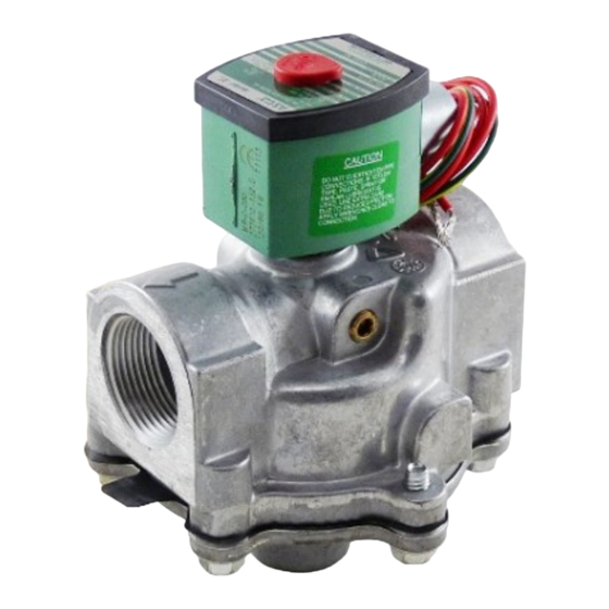
DESCRIPTION
Series 8214 valves are 2--- way normally open diaphragm--- type
solenoid valves designed for fuel gas service. Valve bodies are made
of rugged aluminum with trim and internal parts made of steel and
stainless steel. Series 8214 valve may be provided with a general
purpose, general purpose junction box or watertight/explosionproof
solenoid depending upon basic valve construction.
Valve catalog numbers with Suffix C have an integral electrical and
visual position indicator and proof --- of --- closure construction.
The position indicator gives visual indication of Open and Shut
positions by means of a small ball. The ball travels up and down in
a transparent holder between labels Open and Shut. Electrical
indication is accomplished by the operation of a single pole single
throw reed switch. Reed switch contact is open when solenoid is
de --- energized; closed when energized.
Provisions for Pressure and Seat Leakage Testing
Series 8214 valves are provided with a 1/8 NPT tapped and plugged
hole for downstream seat leakage testing.
frequency shall be at least annually in accordance with NFPA--- 86
or original equipment manufacturer recommendations. Testing is
also required after valve disassembly and reassembly for
inspection, cleaning or rebuilding. See Testing for Internal (Seat)
Leakage section and refer to Figure 3.
OPERATION
Normally Open
: Valve is open when solenoid is de--- energized;
closed when energized.
Operating Pressure Differential
S Minimum 0 psig
INSTALLATION
Check nameplate for correct catalog number, pressure, voltage,
frequency, and service. Never apply incompatible fluids or exceed
pressure rating of the valve. Installation and valve maintenance to be
performed by qualified personnel.
ASCO Valves
R
ASCO Valve, Inc.
50 Hanover Road, Florham Park, New Jersey 07932
E
R
FUEL GAS SERVICE
Leakage testing
S
Maximum 5 psig
E225861--- 04/12
I&M No. V 7466_Sec1 R3
Temperature Limitations
For valve ambient and fluid temperatures, refer to chart below.
Catalog
Insulation
Numbers }
Class
8214G38
8214G54
8214G64
F or H
8214G74
8214G84
} Includes catalog numbers with or without Suffix C.
Positioning
Valves with ¾, 1, 1 ¼, or 1 ½, NPT connections are designed to
perform properly when mounted in any position. The 2 NPT valves
may be mounted with solenoid in any position from horizontal to
vertical and upright. However, for optimum life and performance,
the solenoid on all sizes should be mounted vertically and upright to
reduce the possibility of foreign matter accumulating in the solenoid
base sub--- assembly area.
Piping
Connect piping to valve according to markings on valve body. Apply
pipe compound sparingly to male pipe threads only. If applied to
valve threads the compound may enter the valve and cause
operational difficulty. Avoid pipe strain by properly supporting and
aligning piping. When tightening the pipe, do not use valve or
solenoid as a lever. Locate wrenches applied to valve body or piping
as close as possible to connection point. Valves should be checked for
external leakage at piping connections after installation, see Testing
for External Leakage section.
CAUTION: To avoid damage to the valve body,
DO NOT OVERTIGHTEN PIPE CONNECTIONS. If
PTFE tape paste, spray or similar lubricant is
used, use extra care when tightening due to
reduced friction.
CAUTION:
To protect the solenoid valve,
install a strainer or filter, suitable for the service
involved, in the inlet side as close to the valve as
possible.
Clean periodically depending on
service conditions. See ASCO Series 8600 and
8601 for strainers.
All Rights Reserved.
www.ascovalve.com
SERIES
8214
Minimum and
Maximum
Ambient and Fluid
Temperatures
--- 40_F (--- 40_C) to 140_F (60_C)
I&M No. V 7466 R3
Page 1 of 7 (Section 1 of 2)
Advertisement

Related Manuals for Asco 8214G54


Summary of Contents for Asco 8214G54
- Page 1 Installation and valve maintenance to be possible. Clean periodically depending on performed by qualified personnel. service conditions. See ASCO Series 8600 and 8601 for strainers. ASCO Valves I&M No. V 7466 R3 All Rights Reserved.
-
Page 2: Maintenance
S Excessive Leakage: Disassemble valve and clean all parts. If parts extinguish all open flames and avoid any type worn or damaged install a complete ASCO Rebuilt Kit or replace valve. of sparking or ignition. - Page 3 WARNING: Some gas may be released to Parts marked with an asterisk (*) in the exploded view are supplied in Rebuild Kits. When Ordering Rebuild Kits for ASCO valves, order the atmosphere when the pipe plug is the Rebuild Kit number stamped on the valve nameplate. If the removed.
- Page 4 Notes: ¡ Thread all parts by hand as far as possible. Then torque evenly in a crisscross manner where applicable. © Lubricate these parts if a rebuild kit is not installed. I&M No. V 7466 R3 Page 4 of 7 (Section 1 of 2) ASCO Valve, Inc. 50 Hanover Road, Florham Park, New Jersey 07932 www.ascovalve.com...
- Page 5 NOTICE: See separate solenoid installation and maintenance instructions for information on: Wiring, Solenoid Temperature, Causes of Improper Operation, and Solenoid Replacement. Indicates parts supplied solenoid base sub---assembly in ASCO Rebuild Kit solenoid base gasket valve body Partial view of valve body...
- Page 6 Figure 2. Series 8214 valve with watertight position indicator. Page 6 of 7 (Section 2 of 2) I&M No. V 7466 R3 ASCO Valve, Inc. 50 Hanover Road, Florham Park, New Jersey 07932 www.ascovalve.com...
- Page 7 Normally Closed Shutoff Valves UPSTREAM DOWNSTREAM MAIN GAS LINE Figure 3. Testing for internal (seat) leakage. I&M No. V 7466 R3 Page 7 of 7 (Section 2 of 2) ASCO Valve, Inc. 50 Hanover Road, Florham Park, New Jersey 07932 www.ascovalve.com...
Need help?
Do you have a question about the 8214G54 and is the answer not in the manual?
Questions and answers