Table of Contents
Advertisement
Quick Links
Installation & Maintenance Instructions
1/4I, 3/8I, 1/2I, 3/4I, OR 1I NPT - 1/4I, 3/8I, OR 3/4I ORIFICE
SINGLE SOLENOID - AIR OR INERT GAS SERVICE
IMPORTANT: See Installation and Maintenance Instructions, Form No. V6862 for exploded isometric views.
IMPORTANT:
See separate solenoid installation and
maintenance instructions for information on: Wiring,
Solenoid temperature, Causes of Improper Operation, Coil or
Solenoid Replacement.
DESCRIPTION
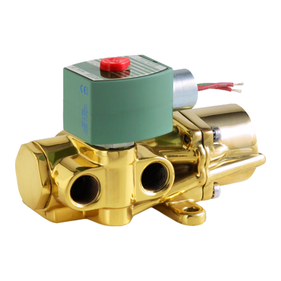
Series 8344 valves are heavy duty, 2-position, 4-way valves
with poppet type seats and discs to provide tight seating. The
main valve discs are power driven in both directions by line
pressure. No return springs are required. The valves are made
of forged brass with stainless steel, brass, and copper internal
parts; elastomers are Buna N. The valves may be provided with
a low power or intrinsically safe solenoid.
OPERATION
Solenoid De-energized: Flow is from Pressure P to Cylinder B
and from Cylinder A to Exhaust E. Slight pilot exhaust is also
apparent.
Solenoid Energized: Flow is from Pressure P to Cylinder A and
from Cylinder B to Exhaust E.
IMPORTANT: Minimum operating pressure differential is 10
psi.
Flow Diagrams
De-energized
Cyl. B
Cyl. A
Pilot
Exh.
Press. Exh.
P
E
INSTALLATION
Check nameplate for correct catalog number, pressure,
voltage, frequency, and service. Never apply incompatible
fluids or exceed pressure rating of the valve. Installation and
valve maintenance to be performed by qualified personnel.
Temperature Limitation
Fluid and ambient temperature range: -4_F to +140_F.
Future Service Considerations
Provision should be made for performing seat leakage, external
leakage,
and operational tests on the valve with a
nonhazardous, noncombustible fluid after disassembly and
reassembly.
e
ASCO Valves
2-POSITION, 4-WAY SOLENOID VALVES
Energized
Cyl. B
Cyl. A
Pilot
Exh.
Press. Exh.
P
E
MCMXCIII All Rights Reserved.
Positioning
Valve may be mounted in any position.
Mounting
For mounting valve refer to Figure 1.
Pipe
Length L "*
Size
NPT
Inches
mm
Inches
1/4I
1 7/8
47,6
2 13/32
3/8I
2 5/8
2 5/8
66,6
66 6
1/2I
3/4I
3 7/8
3 7/8
98,4
98 4
3 13/16
3 13/16
1I
Figure 1. Series 8344 valve body mounting dimensions.
Piping
There is pilot exhaust from the top of the solenoid when the
valve is in the de-energized mode. The pilot exhaust may be
connected to the main exhaust if the air or inert gas cannot be
exhausted directly to the atmosphere. Connect piping or tubing
to valve according to markings on valve body. Refer to flow
diagrams in OPERATION section.
CAUTION: To avoid damage or accidental disengagement
of cartridge assembly from valve body, hold cartridge assembly
securely by wrenching flats when installing or removing piping
at top of solenoid.
Apply pipe compound sparingly to male pipe threads only. If
applied to valve threads, the compound may enter the valve and
cause operational difficulty. Avoid pipe strain by properly
supporting and aligning piping. When tightening the pipe, do
not use valve or solenoid as a lever. Locate wrenches applied
to valve body or piping as close possible to connection point.
To insure proper operation of the valve, the pressure and
exhaust lines must be full area without restriction. A minimum
differential pressure (10 psi), as stamped on the nameplate
must be maintained between pressure and exhaust at the
moment of shifting. Air reservoirs must have adequate capacity
to maintain this minimum pressure during shifting. To check
pressure during shifting, install a pressure gauge in the pressure
piping as close to the valve as possible.
Printed in U.S.A.
50-60 Hanover Road, Florham Park, New Jersey 07932
SERIES
8344
Form No. V6861R1
Holes D"*
Width W" *
Dia. ∅
mm
Inches
61,1
9/32
3 1/8
3 1/8
79 3
79,3
11/32
11/32
96 8
96,8
11/32
11/32
Page 1 of 4
mm
7,1
8,7
8 7
8,7
8 7
Advertisement
Table of Contents

Subscribe to Our Youtube Channel
Related Manuals for Asco 8344 Series


Summary of Contents for Asco 8344 Series
- Page 1 Page 1 of 4 MCMXCIII All Rights Reserved. Printed in U.S.A. ASCO Valves 50-60 Hanover Road, Florham Park, New Jersey 07932...
- Page 2 Thoroughly clean all parts. If parts Solenoid are worn or damaged, install a complete ASCO Rebuild Kit. Causes Of Improper Operation S Incorrect Pressure: Check valve pressure. Pressure to valve must be within range specified on nameplate.
- Page 3 17. All parts are now accessible to clean or replace. If parts are size. However, the lower gasket is made of a softer worn or damaged, install a complete ASCO Rebuild Kit. material. 11. Place disc holder sub-assembly into insert. Install insert...
- Page 4 5. A 4-40 machine screw provided in ASCO Rebuild Kit C. Slip piston guide with gaskets onto shaft. serves as a self-tapping screw to remove insert from body. D. Position shaft gasket on shaft. Thread screw a few turns into through hole located in flat E.
Need help?
Do you have a question about the 8344 Series and is the answer not in the manual?
Questions and answers