Table of Contents
Advertisement
Available languages
Available languages
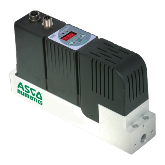
2-Port Flow Control Valve with Digital Electronics
2-Wege-Durchfl ussregelventil mit Digitaler Technik
Vanne de régulation de débit à 2 orifices
Series / Baureihe / Série 607
F
LOWTRONIC
Electronique numérique
D
Installation manual
Installation manual
Installationshandbuch
Installationshandbuch
Manuel d'installation
Manuel d'installation
IM14156.R4
GB
DE
FR
Advertisement
Chapters
Table of Contents

Related Manuals for Asco FLOWTRONIC D 60701073


Summary of Contents for Asco FLOWTRONIC D 60701073
- Page 1 LOWTRONIC 2-Port Flow Control Valve with Digital Electronics 2-Wege-Durchfl ussregelventil mit Digitaler Technik Vanne de régulation de débit à 2 orifices Electronique numérique Series / Baureihe / Série 607 Installation manual Installation manual Installationshandbuch Installationshandbuch Manuel d’installation Manuel d’installation IM14156.R4...
-
Page 2: Table Of Contents
The information in this manual is subject to change without notice. In no event shall ASCO NUMATICS be liable for technical or editorial errors or omissions. Neither is any liability assumed for accidental or consequential damages arising out of or in connection with the supply or use of the information contained herein. -
Page 3: Description
LOwTRONIC An auto-tune function and the ASCO FlowCom PC software provide easy start-up. Diagnosis of the F LOwTRONIC made possible over the integrated LEDs and the ASCO FlowCom PC software ASCO FlowCom. The F LOwTRONIC available with or without LED display and operating buttons. -
Page 4: Manual Setpoint Adjustment
INSTALLATION MANUAL SETPOINT ADJUSTMENT (HAND) After an interruption in the power supply, press both arrow buttons located beneath the display during power up to switch to the manual mode. The operating mode is indicated by the letters “H n d” in the display. The "H n d"... -
Page 5: Electrical Connection
INSTALLATION ELECTRICAL CONNECTION 5-pin M12 female connector (view on soldered side) M12 connector Valve Control +24V supply voltage Supply voltage GND 250 Ohm at current setpoint Setpoint 0-10V (or 0-20 / 4-20mA) Setpoint GND (only for 6-wire cable) Analog output: Feedback Only at current output: 0-10V... -
Page 6: Pneumatic Connection
INSTALLATION PNEUMATIC CONNECTION The air flow is from port 1 in the direction of the arrow. Pressure supply Outlet Inch screw connections (pipe threads) must be used. Each screw connections must be lined with a fitting synthetic sealing disc. Do not use Teflon sealing tape or hemp as they may get inside the valve and damage it. The diameter of the pneumatic lines must be adjusted to the nominal diameter of the valve. -
Page 7: Technical Characteristics
1. Press and hold the AUTOTUNE button, switch the supply voltage off and on again, and release the AUTOTUNE but- ton. 2. Over the ASCO-FlowCom operating software. 3. If the appropriate option has been selected over the operating software, AUTOTUNE can be activated over the digital input (M12, Pin 5). -
Page 8: Accessories
INSTALLATION ACCESSORIES Description CODES software "ASCO-FlowCom-Light" - CD-ROM 881 00 895 LOwTRONIC software "ASCO-FlowCom-Expert" - CD-ROM 881 00 896 LOwTRONIC G 1/2" adapter 881 60 701 881 60 702 G 3/8" adapter 881 00 897 USB cable for connection of F... -
Page 9: Im14156
INSTALLATION Weight: 0,85 kg Orifice size 2 - 6 mm (5-1000 l/min) M12x1 connector M12x1 USB connection * (optional) * (optional) G1/2" adapter (88160701) G1/2" adapter (88160701) or G3/8" adapter (88160702) or G3/8" adapter (88160702) Mounting with M4 for earth screw 4xM4 screws from top or 4xM5 from bottom IM14156-9... - Page 10 INSTALLATION ASCO Numatics GmbH Otto-Hahn-Straße 7-11 75248 Ölbronn-Dürrn Germany Tel: +49 7237 996-0 Email: asconumatics-de@emerson.com www.asconumatics.eu IM14156-10...
-
Page 11: De Deutsche Version
2-Wege-Durchfl ussregelventil mit Digitaler Technik Baureihe 607 LOWTRONIC Installationshandbuch IM14156-DE.R4... - Page 12 DIE IN DIESEM HANDBUCH ENTHALTENEN ANGABEN KÖNNEN OHNE VORHERIGE ANKÜNDIGUNG GEÄNDERT WERDEN. ASCO NUMATICS übernimmt keinerlei Haftung für technische oder redaktionelle Fehler oder Ungenauigkeiten oder für versehentlich entstehende Schäden oder Folgeschäden, die durch die Bereitstellung dieses Handbuchs oder aus der Anwendung desselben entstehen.
-
Page 13: Beschreibung
Applikationen angepasst werden. Über Autotune und eine zusätzlichen PC-Software ASCO FlowCom (AFC) erfolgt die komfortable Inbetriebnahme. Eine Diagnose des F ist ebenfalls LOwTRONIC über die eingebauten LEDs oder über die PC-Software ASCO FlowCom möglich. F ist mit und ohne LOwTRONIC LED-Anzeige und Bedientasten lieferbar. -
Page 14: Manuelle Sollwert-Verstellung
INSTALLATION MANUELLE SOLLWERT-VERSTELLUNG (HANDBETRIEB) Wird die Versorgungsspannung unterbrochen, wird nach einem erneuten Zuschalten der Versorgungsspannung und bei gleichzeitigen Drücken der beiden Pfeiltasten unterhalb des Displays in den Betriebszustand „Handbetrieb“ gewechselt. Dieser Betriebszustand wird im Display durch die Zeichen "H n d" angezeigt. Die Anzeige "H n d"... -
Page 15: Elektrischer Anschluss
INSTALLATION ELEKTRISCHER ANSCHLUSS =max. 200mA/4,8W 1. Das Ventil darf nur mit einer Versorgungsspannung von 24VDC +15%/-10% und einer maximalen Welligkeit von 10% betrieben werden. (Eine Einspeisung über Diodenbrücke ist nicht gestattet). Überspannungen und Welligkeiten au- ßerhalb dieser Toleranzen können zu einer Beschädigung der Elektronik führen. 2. -
Page 16: Pneumatischer Anschluss
INSTALLATION PNEUMATISCHER ANSCHLUSS Die pneumatische Durchflussrichtung ist von Anschluss 1 in Pfeilrichtung. Druckversorgung Ausgang Es sind zöllige Verschraubungen (Rohrgewinde) zu verwenden. Jede Verschraubung ist mit einem passenden Kunststoffdichtring zu unterlegen. Teflondichtband und Hanf dürfen nicht verwendet werden, da sie in das Innere des Ventils gelangen können. Der Querschnitt der Pneumatikleitungen ist der Nennweite des Ventils anzupassen. -
Page 17: Technische Daten
1. Die Taste AUTOTUNE gedrückt halten, die Versorgungsspannung aus- und wieder einschalten und die Taste anschlie- ßend loslassen. 2. Über die Bediensoftware ASCO-FlowCom. 3. Falls über die Bediensoftware die entsprechende Option ausgewählt wurde, kann AUTOTUNE über den digitalen Eingang (M12, Pin 5) gestartet werden. -
Page 18: Zubehör
INSTALLATION ZUBEHÖR Beschreibung Bestell-Code -Software "ASCO-FlowCom-Light" auf CD-ROM 881 00 895 LOwTRONIC -Software "ASCO-FlowCom-Expert" auf CD-ROM 881 00 896 LOwTRONIC G 1/2"-Adapter 881 60 701 G 3/8"-Adapter 881 60 702 USB-Verbindungskabel zwischen F und PC 881 00 897 LOwTRONIC Gerade M12 Leitungsdose, 5-polig, mit Schraubklemmen... - Page 19 INSTALLATION Gewicht: 0,85 kg Nennweite 2 - 6 mm (5-1000 l/min) * (optional) * (optional) G1/2"-Adapter (88160701) G1/2"-Adapter (88160701) oder G3/8"-Adapter (88160702) oder G3/8"-Adapter (88160702) IM14156-19...
- Page 20 INSTALLATION ASCO Numatics GmbH Otto-Hahn-Straße 7-11 75248 Ölbronn-Dürrn Germany Tel: +49 7237 996-0 Email: asconumatics-de@emerson.com www.asconumatics.eu IM14156-20...
-
Page 21: Fr Version Française
Vanne de régulation de débit à 2 orifi ces Electronique numérique ÉRIE LOWTRONIC Manuel d'installation IM14156-FR.R4... - Page 22 NOTES Les informations contenues dans le présent manuel sont susceptibles d’être modifiées sans préavis. ASCO NUMATICS ne peut être tenu responsable des omissions techniques ou rédactionnelles, ni des dommages accidentels ou consécutifs à la fourniture ou l’utilisation du présent document.
-
Page 23: Description
être adapté à diverses applications grâce à l'électronique numérique configurable par PC via LOwTRONIC l'interface USB. La fonction auto-tune et le logiciel ASCO FlowCom permettent une mise en service simple et rapide. Le diagnostic du F se fait au moyen des LEDs intégrées au produit ou via logiciel ASCO FlowCom. Le LOwTRONIC est disponible avec ou sans affichage LED et boutons en façade. -
Page 24: Réglage Manuel Du Débit (Mode Manuel)
INSTALLATION REGLAGE MANUEL DE LA CONSIGNE (MODE MANUEL) Pour passer en mode Manuel après une coupure de l’alimentation électrique, appuyer sur les deux boutons-pous- soirs à flèche qui se trouvent sous l’affichage pendant la remise sous tension. Le mode de fonctionnement est indiqué... -
Page 25: Raccordement Électrique
INSTALLATION RACCORDEMENT ELECTRIQUE Connecteur femelle M12 5 broches (vue du côté soudure) Connecteur M12 Vanne Contrôle Alimentation +24V Masse d’alimentation 250 Ohm à la consigne courante Consigne 0-10V (ou 0-20 / 4-20mA) Masse consigne (seulement pour câble à 6 fils) Sortie analogique: Retour Seulement pour... -
Page 26: Raccordement Pneumatique
INSTALLATION RACCORDEMENT PNEUMATIQUE Le sens de circulation de l'air est indiqué par la flèche. Alimentation Sortie Les 2 orifices sont disponibles avec un taraudage Gaz. Chaque connexion vissée doit être montée avec un joint d’étanchéité. Ne pas utiliser de ruban d’étanchéité en PTFE ou de chanvre car ils pourraient pénétrer à l’intérieur de la vanne et l’endommager. -
Page 27: Caractéristiques Techniques
1. En maintenant enfoncée la touche AUTOTUNE, couper puis rétablir l'alimentation en tension, et relâchez ensuite la touche. 2. En se servant du logiciel d'exploitation ASCO-FlowCom. 3. Une fois l'option appropriée sélectionnée en passant par le logiciel d'exploitation, AUTOTUNE peut être démarré en passant par l'entrée numérique (M12, Pin 5). -
Page 28: Accessoires
INSTALLATION ACCESSOIRES Description CODES Logiciel «ASCO-FlowCom-Light» pour le F - CD-ROM 881 00 895 LOwTRONIC Logiciel «ASCO-FlowCom-Expert» pour le F - CD-ROM 881 00 896 LOwTRONIC Adaptateur G 1/2" 881 60 701 Adaptateur G 3/8" 881 60 702 881 00 897 Câble USB pour le raccordement du F... - Page 29 INSTALLATION Masse: 0,85 kg Diamètre nominal 2 - 6 mm (5-1000 l/min) Connecteur M12x1 Connecteur M12x1 USB *(optionnel) *(optionnel) Adaptateur G1/2 (88160701) Adaptateur G1/2 (88160701) ou adaptateur (88160702) ou adaptateur (88160702) Montage avec 4 vis M4 par le dessus M4 pour vis de Terre Ou 4 vis M5 par le dessous IM14156-29...
- Page 30 YOUR NOTES / IHRE NOTIZEN / VOS NOTES IM14156-30...
- Page 31 YOUR NOTES / IHRE NOTIZEN / VOS NOTES IM14156-31...
- Page 32 INSTALLATION ASCO Numatics GmbH Otto-Hahn-Straße 7-11 75248 Ölbronn-Dürrn Germany Tel: +49 7237 996-0 Email: asconumatics-de@emerson.com www.asconumatics.eu IM14156-32...
Need help?
Do you have a question about the FLOWTRONIC D 60701073 and is the answer not in the manual?
Questions and answers