Table of Contents
Advertisement
Quick Links
Installation & Maintenance Instructions
IMPORTANT: See separate solenoid installation
and maintenance instructions for information on:
Wiring, Solenoid Temperature, Causes of Improp
er Operation, Coil, or Solenoid Replacement.
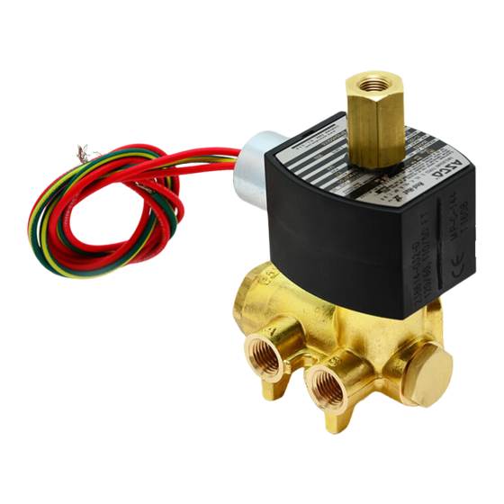
DESCRIPTION
Series 8345 valves are 2- position 4-way solenoid
valves designed for air or inert gas service. Valve
bodies are made of rugged brass. The valves may
be provided with a low power or intrinsically safe
solenoid.
OPERATION
Solenoid De-energized: Flow is from Pressure P
to Cylinder A and from Cylinder B to Exhaust EB.
Exhaust EA is closed.
Solenoid Energized: Flow is from Pressure P to
Cylinder B and from Cylinder A to Exhaust EA.
Exhaust EB is closed.
IMPORTANT:
Minimum operating pressure
differential is 10 psi.
Flow Diagrams
De-energized
EB
P
B EA A
INSTALLATION
Check nameplate for correct catalog number,
pressure, voltage, frequency, and service. Never
apply incompatible fluids or exceed pressure
rating of the valve.
Maintenance to be performed by qualified
personnel.
e
ASCO Valves
2 - POSITION 4-WAY SOLENOID VALVES
BRASS CONSTRUCTION
1/4I NPT - AIR OR INERT GAS SERVICE
Energized
EB
B EA A
Installation and valve
MCMXCIII All Rights Reserved.
Temperature Limitations
Fluid and ambient temperature range: -4_F to
+140_F.
Future Service Considerations
Provision should be made for performing seat
leakage, external leakage, and operational tests on
the valve with a nonhazardous, noncombustible
fluid after disassembly and reassembly.
Positioning
Valve may be mounted in any position.
Mounting
For mounting valve body refer to Figure 1.
[41,3]
1 5/8
Figure 1. Dimensions for mounting valve body.
Piping
There are two exhaust ports EA and EB. Exhaust
P
ports EA and EB may be connected to a common
exhaust if the air or inert gas cannot be exhausted
directly to the atmosphere. Connect piping or
tubing to valve according to markings on valve
body. Refer to flow diagrams in OPERATION
section.
CAUTION: To avoid damage or accidental
disengagement of cartridge assembly from valve
body, hold cartridge assembly securely by
wrenching flats when installing or removing
piping at Port EB.
Printed in U.S.A.
50-60 Hanover Road, Florham Park, New Jersey 07932
SERIES
8345
Form No.V6865R1
[7,9]
5/16
[5,6]
7/32
2 slots for mounting
Page 1 of 4
Advertisement
Table of Contents

Related Manuals for Asco 8345 Series


Summary of Contents for Asco 8345 Series
- Page 1 Installation and valve wrenching flats when installing or removing maintenance to be performed by qualified piping at Port EB. personnel. Page 1 of 4 MCMXCIII All Rights Reserved. Printed in U.S.A. ASCO Valves 50-60 Hanover Road, Florham Park, New Jersey 07932...
- Page 2 In the extreme case, valve malfunction. faulty valve operation will occur and the valve may fail to shift. Clean filter when cleaning the valve. Page 2 of 4 Form No.V6865R1 ASCO Valves 50-60 Hanover Road, Florham Park, New Jersey 07932...
- Page 3 Parts marked with an asterisk (*) in the exploded view are supplied in Rebuild Kits. When Ordering 7. Clean valve and install a complete ASCO Rebuild Kit. Rebuild Kits for ASCO valves, order the Rebuild Kit number stamped on the valve nameplate. If the...
- Page 4 (mouth or open end to face end plug) Indicates parts supplied in Rebuild Kit end plug gasket end plug Figure 3. Series 8345 without solenoid. Page 4 of 4 Form No.V6865R1 ASCO Valves 50-60 Hanover Road, Florham Park, New Jersey 07932...
Need help?
Do you have a question about the 8345 Series and is the answer not in the manual?
Questions and answers