Table of Contents
Advertisement
Quick Links
Installation & Maintenance Instructions
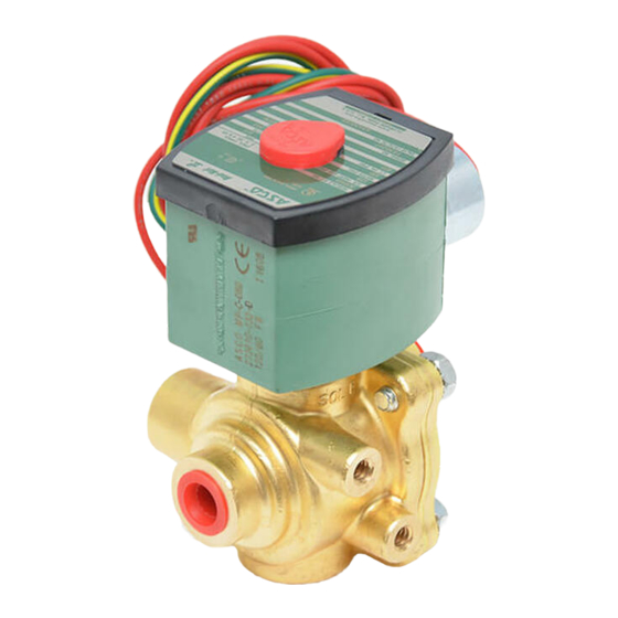
4-WAY DIRECT-ACTING SOLENOID VALVES
BRASS AND STAINLESS STEEL CONSTRUCTION
NOTICE: See separate solenoid installation and maintenance
instructions
for
information
Temperature, Causes of Improper Operation, Coil or Solenoid
Replacement.
DESCRIPTION
Series 8342 valves are 4-way direct-acting solenoid valves
that require no minimum operating pressure and no minimum
flow for operation. Valves are made of rugged brass or stainless
steel and have a sliding resilient seal for tight seating. Standard
valves have a general purpose solenoid enclosure. Valves may
be provided with a combination explosionproof/watertight
solenoid enclosure.
Series 8342 valves with Suffix P in the catalog number are
designed specifically for dry inert gas or non-lubricated air
service.
OPERATION
Solenoid de-energized: Flow is from Pressure P to Cylinder A
and from Cylinder B to Exhaust E.
Solenoid energized: Flow is from Pressure P to Cylinder B and
from Cylinder A to Exhaust E.
NOTE: No minimum operating pressure required.
Flow Diagrams
Solenoid De-energized
SOL.
P
PRESS.
A
EXH.
B
E
NOTE: For 3-way application, one cylinder port can be
plugged. Plug Cylinder A for normally closed operation or
Cylinder B for normally open operation.
IMPORTANT: Flow controls or regulators may be placed at
any of the port connection without adversely affecting valve
operation.
Metering Device
(Optional feature)
Valves with suffix M in the catalog number are provided with a
built-in metering device (flow control) for each cylinder
connection. To adjust metering device, release locknut by
turning it counterclockwise. To increase flow, turn metering
stem clockwise.
To reduce flow, turn metering stem
counterclockwise.
After adjusting to desired flow, hold
metering stem and tighten locknut. The metering stem closest
to the solenoid controls Cylinder A; the adjacent metering stem
controls Cylinder B.
e
50 Hanover Road, Florham Park, New Jersey 07932
1/4I AND 3/8I NPT - 3/16I ORIFICE
on:
Wiring,
Solenoid
Solenoid Energized
SOL.
P
PRESS.
EXH.
E
E21903 - 1/12
MM
All Rights Reserved.
Manual Operation
Manual operator allows manual operation when desired or
during an electrical power outage. Depending upon valve
requirements, two types of manual operators are available:
Momentary Push Type (Suffix MO) Manual Operator
To engage push type manual operator, push stem at base of
valve body upward as far as possible. Valve will now be in the
same position as when the solenoid is energized. To disengage
manual operator, release stem. Manual operator will return to
original position.
Maintained Screw Type (Suffix MS) Manual Operator
To engage screw type manual operator, push red knob upward
towards valve body and turn it clockwise until flow from port is
stopped. Valve will now be in the same position as when
solenoid is energized.
CAUTION: If manual operator is not turned clockwise
after pushing upward to engage, leakage at exhaust port
may occur.
To disengage manual operator and return valve to the
de-energized position, turn red knob counterclockwise
allowing stem to disengage and drop.
CAUTION: For valve to operate electrically, manual
operator must be fully disengaged.
Check nameplate for correct catalog number, pressure,
voltage, frequency and service.
fluids or exceed pressure rating of the valve. Installation and
valve maintenance to be performed by qualified personnel.
Future Service Considerations
A
Provision should be made for performing seat leakage, external
leakage, and operational tests on the valve with a
B
nonhazardous, noncombustible fluid after disassembly and
reassembly.
Temperature Limitations
For maximum valve ambient and fluid temperatures, refer to
chart below. Check catalog number prefix and watt rating on
nameplate.
Catalog
Watt
Number
Rating
Prefix
None, DP
or KP
20
20
HB or KB
None, KP ,
SP or SD
20 1
20.1
HB, KB,
SS or SV
Printed in U.S.A.
www.ascovalve.com
I&M No. V
SERIES
8342
Form No. V6319R3
INSTALLATION
Never apply incompatible
Max.
Coil
Ambient
Class
Temp.
77_F
F
(25_C)
125_F
H
(51.7_C)
125_F
F
(51.7_C)
140_F
H
(60_C)
I&M No. V 6319 R4
Page 1 of 4
R
Max.
Fluid
Temp.
160 F
160_F
(71_C)
160 F
160_F
(71_C)
Advertisement
Table of Contents

Related Manuals for Asco 8342 series


Summary of Contents for Asco 8342 series
- Page 1 I&M No. V Installation & Maintenance Instructions SERIES 4-WAY DIRECT-ACTING SOLENOID VALVES 8342 BRASS AND STAINLESS STEEL CONSTRUCTION 1/4I AND 3/8I NPT - 3/16I ORIFICE Form No. V6319R3 Manual Operation NOTICE: See separate solenoid installation and maintenance Manual operator allows manual operation when desired or instructions information Wiring,...
- Page 2 Thoroughly clean all parts. If parts any position. However, for optimum life and performance, the are worn or damaged, install a complete ASCO Rebuild Kit. solenoid should be mounted vertically and upright to reduce the possibility of foreign matter accumulating in the solenoid Causes of Improper Operation base sub-assembly area.
- Page 3 Rebuild Kits. When Ordering Rebuild Kits for core spring guide. ASCO valves, order the Rebuild Kit number stamped on the 8. Replace solenoid base sub-assembly and torque to valve nameplate. If the number of the kit is not visible, order 175 ±...
- Page 4 17 ± 1,1 solenoid base sub-assembly core spring guide core spring Suffix P" Construction Indicates Parts Supplied In ASCO Rebuild Kits core sleeve spring core with rider rings bonnet gasket body seat gasket body seat (exhaust) sleeve/disc/spring assembly end cap seat gasket...
Need help?
Do you have a question about the 8342 series and is the answer not in the manual?
Questions and answers