Asco 8316 Installation & Maintenance Instructions
3-way solenoid valves normally closed and normally open operation 3/8” , 1/2” and 3/4” npt
Hide thumbs
Also See for 8316:
- Operating manual (7 pages) ,
- Installation & maintenance instructions manual (10 pages)
Table of Contents
Advertisement
Quick Links
Installation & Maintenance Instructions
NORMALLY CLOSED AND NORMALLY OPEN OPERATION
NOTICE: See separate solenoid installation and maintenance
instructions for information on: Wiring, Solenoid Temperature, Causes
of Improper Operation, and Coil Replacement.
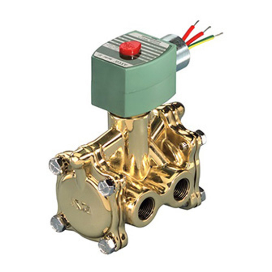
DESCRIPTION
Series 8316 are 3-way, diaphragm-operated solenoid, pilot-controlled
valves. Valves are made of brass with only four moving parts: a core
assembly, two diaphragm assemblies and a disc holder sub-assembly.
Valves may be provided with a general purpose, explosionproof/watertight
solenoid enclosures.
Series 8316 valves with Suffix "P" in the catalog number are designed for
dry inert gas and non-lubricated air service.
OPERATION
Normally Open
Solenoid De-energized: Flow is from Pressure "P" to Cylinder "A". Exhaust
Port "E" is closed.
Solenoid Energized: Flow is from Cylinder "A" to Exhaust "E". Pressure
Port "P" is closed.
Normally Closed
Solenoid De-energized: Flow is from Cylinder "A" to Exhaust "E". Pressure
Port "P" is closed.
Solenoid Energized: Flow is from Pressure "P" to Cylinder "A". Exhaust
Port "E" is closed.
Flow Diagrams
NORMALLY OPEN
UNLATCHED
LATCHED
(CYL)
(CYL)
A
A
E
P
E
P
(EXH)
(PRESS)
(EXH)
(PRESS)
IMPORTANT: A minimum operating pressure differential of 10 psi is
required; however, valve vents to 0 psi.
Manual Operator
Manual operator allows manual operation when desired or during an
electrical power outage. To operate valve manually, rotate manual operator
stem clockwise 1800. Valve will now be in the same position as when the
solenoid is energized. Rotate manual operator stem counterclockwise 1800
before operating valve electrically.
INSTALLATION
Check nameplate for correct catalog number, pressure, voltage, frequency,
and service. Never apply incompatible fluids or exceed pressure rating of
the valve. Installation and valve maintenance to be performed by qualified
personnel.
Temperature Limitations
For maximum valve ambient and fluid temperatures, refer to following chart
or as limited by by hazardous location (explosive atmosphere) solenoid
approvals. See solenoid installation and maintenance instructions. Check
catalog number prefix and watt rating on nameplate.
Valves with design change letter "G" within the catalog number (example:
8316G014) have a maximum fluid temperature of 1800F AC and 1200F DC
(except hazardous location solenoid - example: prefix EF or EV). Refer to
separate solenoid instruction sheet provided for ambient temperature.
Page 1 of 4
ASCO Valve, Inc. 160 Park Avenue, Florham Park, New Jersey 07932
©
3-WAY SOLENOID VALVES
3/8" , 1/2" AND 3/4" NPT
NORMALLY CLOSED
UNLATCHED
LATCHED
(CYL)
(CYL)
A
A
E
P
E
P
(EXH)
(PRESS)
(EXH)
(PRESS)
E291076 - 07/2019
Positioning
This valve is designed to perform properly when mounted in any position.
However, for optimum life and performance, the operator movement should
be mounted vertical and upright to reduce the possibility of foreign matter
accumulating in the solenoid base sub-assembly area. Valve with suffix "P"
in the catalog number must be mounted with the solenoid vertical and upright.
Mounting
Refer to Figure 1 for mounting bracket (optional feature) mounting
dimensions.
Piping
Connect piping to valve according to markings on valve body. Refer to flow
diagrams provided. Apply pipe compound sparingly to male pipe threads
only. If applied to valve threads, the compound may enter the valve and
cause operational difficulty. Avoid pipe strain by properly supporting and
aligning piping. When tightening the pipe, do not use valve or solenoid as a
lever. Locate wrenches applied to valve body or piping as close as possible
to connection point.
To ensure proper operation of the valve,the pressure and exhaust lines must
be full area without restriction. A minimum differential pressure as stamped
on the nameplate must be maintained between pressure and exhaust at the
moment of shifting. Air reservoirs must have adequate capacity to maintain
this minimum pressure during shifting. To check pressure during shifting,
install a pressure gauge in the pressure piping as close to the valve as possible.
IMPORTANT: To protect the solenoid valve, install a strainer or filter,
suitable for the service involved in the inlet side as close to the valve as
possible. Clean periodically depending on service conditions. See ASCO
Series 8600 and 8601 for strainers.
Flow Controls (Speed or Metering Devices)
Flow control valves may be added to control cylinder speed. If used, these
flow control valves must be located in Cylinder A piping between the solenoid
valve and the cylinder.
IMPORTANT: Do not install flow controls (speed or metering devices)
or any type of restrictive device in either the Pressure "P" (inlet) or
Exhaust "E" (outlet) ports of the valve. Restricting either of these lines
may cause valve malfunction.
WARNING: To prevent the possibility of death,
personal injury or property damage, turn off electrical
power, depressurize valve, and vent fluid to a safe area
before servicing the valve.
AVERTISSEMENT: Pour éviter tous danger de mort,
de blessure grave ou de dommage matériel, avant
d'intervenir sur la vanne, couper le courant, purger la
vanne dans une zone sécurisée.
NOTE: It is not necessary to remove the valve from the pipeline for repairs.
Cleaning
All solenoid valves should be cleaned periodically. The time between
cleanings will vary depending on the medium and service conditions.
In general, if the voltage to the coil or solenoid is correct, sluggish valve
operation, excessive noise, or leakage will indicate that cleaning is required.
In the extreme case, faulty valve operation will occur and the valve may fail
to shift. Clean strainer or filter when cleaning the valve.
Preventive Maintenance
•
Keep the medium flowing through the valve as free from dirt and foreign
material as possible.
While in service, the valve should be operated at least once a month to
•
ensure proper opening and closing.
Depending on the medium and service condition, periodic inspection
•
of internal valve parts for damage or excessive wear is recommended.
Thoroughly clean all parts. If parts are worn or damaged, install a
complete ASCO Rebuild Kit.
All Rights Reserved.
I&M V_6592_CA
SERIES
8316
MAINTENANCE
I&M V_6592_CA
www.emerson.com
Advertisement
Table of Contents

Subscribe to Our Youtube Channel
Related Manuals for Asco 8316


Summary of Contents for Asco 8316
- Page 1 Apply pipe compound sparingly to male pipe threads only. If applied to valve threads, the compound may enter the valve and Series 8316 valves with Suffix “P” in the catalog number are designed for cause operational difficulty. Avoid pipe strain by properly supporting and dry inert gas and non-lubricated air service.
- Page 2 A 4-40 machine screw provided in the ASCO Rebuild Kit serves as a For valve with external type core springs, remove core assembly, core self-tapping screw to remove insert from body. Turn screw a few turns spring, core guide and rider ring (if present).
- Page 3 I&M No. V_6592_CA Page 3 of 4 ASCO Valve, Inc. 160 Park Avenue, Florham Park, New Jersey 07932 www.emerson.com © ...
- Page 4 I&M No. V_6592_CA Page 4 of 4 ASCO Valve, Inc. 160 Park Avenue, Florham Park, New Jersey 07932 www.emerson.com © ...
Need help?
Do you have a question about the 8316 and is the answer not in the manual?
Questions and answers