Table of Contents
Advertisement
Quick Links
Installation & Maintenance Instructions
NORMALLY CLOSED, NORMALLY OPEN AND UNIVERSAL OPERATION
BRASS AND STAINLESS STEEL CONSTRUCTION
NOTICE:
See
separate
Maintenance instructions for information on:
Solenoid Temperature, Cause of Improper Operation and
Coil Replacement.
DESCRIPTION
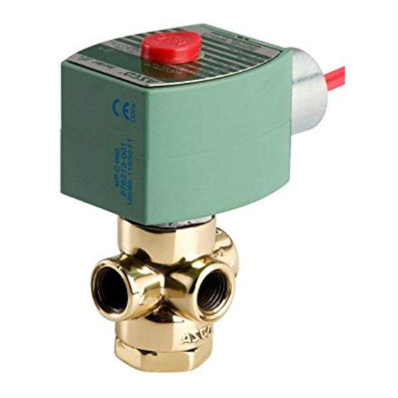
Series 8320 valves are 3---way, direct---acting, miniature sized
solenoid valves with all three pipe connections located in the valve
body. Valves are of rugged brass or stainless steel construction.
Standard valves have a General Purpose NEMA Type 1 Solenoid
Enclosure. Valves may also be equipped with a solenoid enclosure
which is designed to meet NEMA Type 4 --- Watertight, NEMA
Type 7 (C or D) Hazardous Locations --- Class II, Groups E, F or
G. See Installation and Maintenance Instructions, V9531 for
Explosionproof/Watertight Solenoid Enclosures.
OPERATION
Normally Closed: Applies pressure when solenoid is energized;
exhausts pressure when solenoid is de---energized.
Connection "2" to "1" when solenoid is energized. Connection "3"
is closed. Flow is from Connection "1" to "3" when solenoid is
de---energized. Connection "2" is closed. Pressure is applied at
Connection "2".
Normally Open: Applies pressure when solenoid is de---energized;
exhausts pressure when solenoid is energized. Flow is Connection "1"
to "2" when solenoid is energized. Connection "3" is closed. Flow is
from Connection "3" to "1" when solenoid is de---energized.
Connection "2" is closed. Pressure is applied at Connection "3".
Universal: For normally closed or normally open operation, selection
or diversion of pressure can be applied at Connections "1", "2" or "3".
Flow is between Connection "1" to "2" when solenoid is energized.
Connection "3" is closed. Flow is between Connection "1" to "3"
when solenoid is de---energized. Connection "2" is closed. Pressure
may be applied at Connection "1", "2" or "3".
Manual Operation (Valves with Suffix MS): Manual operator allows
manual operation when desired or during an electrical power outage.
The screw type manual operator is in the "off position" when
screwdriver slot is in the horizontal position. To engage manual
operator, rotate stem on the side of the body clockwise 90° . Valve will
now be in the same position as when the solenoid is energized. To
disengage, rotate the stem counterclockwise back to 0° in its original
horizontal position.
Flow Diagram
NORMALLY OPEN
NORMALLY CLOSED
3
2
1
1
DE--- ENERGIZED
DE--- ENERGIZED
PRESSURE AT 2
PRESSURE AT 3
3
2
1
1
ENERGIZED
ENERGIZED
PRESSURE AT 3
PRESSURE AT 2
ASCO Valves
R
ASCO Valve, Inc.
50 Hanover Road, Florham Park, New Jersey 07932
E
R
3-- WAY MINIATURE SIZED SOLENOID VALVES
1/8 NPT -- 3/64, 1/16, 3/32 AND 1/8 ORIFICE
solenoid
installation
UNIVERSAL
3
3
2
1
DE--- ENERGIZED
PRESSURE AT ANY ORIFICE
3
3
2
1
ENERGIZED
PRESSURE AT ANY ORIFICE
and
Check nameplate for correct catalog number, pressure, voltage,
frequency, and service. Never apply incompatible fluids or exceed
pressure rating of the valve. Installation and valve maintenance to be
performed by qualified personnel.
Temperature Limitations
For maximum valve ambient and fluid temperatures, refer to the
following table.
consult factory. Check catalog number prefix and watt rating on
nameplate to determine the maximum temperatures.
n
Constructio
Flow is
AC
DC
[ Catalog Numbers 8320B130, 8320B131, 8320B134, 8320B135,
8320B138, 8320B139, 8320A140, 8320A141, 8320A144, 8320A145,
8320A148 and 8320A149 are limited to a fluid temperature of 60_C
(140_F).
Positioning
This solenoid is designed to perform properly when mounted in
any position. However, for optimum life and performance, the
solenoid should be mounted vertically and upright to reduce the
possibility of foreign matter accumulating in the cartridge assembly
area.
Mounting
For mounting dimensions of mounting bracket, refer to Figure 1.
Piping
Connect piping or tubing to valve according to markings on valve
body. Apply pipe compound sparingly to male pipe threads only.
If applied to valve threads, the compound may enter the valve and
cause operational difficulty.
2
supporting and aligning piping. When tightening the pipe, do not
use valve or solenoid as a lever. Locate wrenches applied to valve
body or piping as close as possible to connection point.
IMPORTANT:
2
strainer or filter, suitable for the service involved, in the inlet
side as close to the valve as possible. Clean periodically
depending on service conditions. See ASCO Series 8600,
8601 and 8602 for strainers.
www.ascovalve.com
I&M No.V6055R3
INSTALLATION
For higher ambient and fluid temperatures,
Watt
Coil
Prefix
Rating
Class
None, DA or
A
S
DB, LB, SB,
H or
6
DF, FT or SF
F
H
HT
None, DP or
[
9
F
SP
None, FT,
A, F
9.7
HT, LB, S or
or H
SF
Avoid pipe strain by properly
To protect the solenoid valve, install a
All Rights Reserved.
E209181--- 05/10
SERIES
8320
Max
Max Fluid
Ambient
Temp
Temp
C
F
C
F
25
77
82
180
50
122
93
200
60
140
93
200
25
77
82
180
25
77
49
120
Page 1 of 3
Advertisement
Table of Contents

Related Manuals for Asco 8320 Series


Summary of Contents for Asco 8320 Series
- Page 1 IMPORTANT: To protect the solenoid valve, install a strainer or filter, suitable for the service involved, in the inlet side as close to the valve as possible. Clean periodically depending on service conditions. See ASCO Series 8600, ENERGIZED ENERGIZED ENERGIZED...
- Page 2 S Excessive Leakage: Disassemble valve and clean all parts. If parts CAUTION: When metal retaining clip disengages, it will spring are worn or damaged, install a complete ASCO Rebuild Kit. upward. Rotate coil to desired position. Replace retaining clip Coil Replacement (Refer to Figure 1) before operating.
- Page 3 Rebuild Kits. When Ordering Rebuild Kits for NOTE: For valves with an Explosionproof/Watertight Solenoid ASCO valves, order the Rebuild Kit number stamped on the enclosure, the solenoid may be assembled as a complete unit. valve nameplate. If the number of the kit is not visible, order by indicating the number of kits required, and the Catalog Number 7.
Need help?
Do you have a question about the 8320 Series and is the answer not in the manual?
Questions and answers