Asco 290 Series General Installation And Maintenance Instructions
Valves with positioner (2/2 and 3/2)
Hide thumbs
Also See for 290 Series:
Table of Contents
Advertisement
Available languages
Available languages
Quick Links
General installation and maintenance instructions
Valves with Positioner
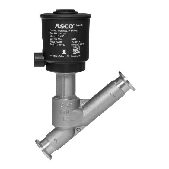
DESCRIPTION (Figs. 1 and 2)
The valves are equipped with a piston-type operator of 50,
63, 90 or 125 mm in diameter. Series 290 normally closed 2/2
valves are equipped with a profi led disc. Series 390 normally
closed 3/2 valves are equipped with a standard disc.
A Positioner
D
positioning unit made of PA (polyamide) 6/6
GF 30% (glass fi bre reinforced) equipped with a metal ca-
ble gland for cable dia. 4,5 - 9 mm is standard fi tted on the
valves. It includes a linear potentiometer, a processor and
two pilot valves.
- Single loop control
- Double loop control for positioner with directly connected
external sensor.
APC software for modifi cation of control parameters is available
for download at: www.asconumatics.eu. The APC software is
required for double loop control.
The Positioner
D
with double-loop control is delivered ex
works with factory settings (positioner). The device must be
mounted on the angle-seat valve and initialised with these
factory settings. The APC software can be used to set the
Positioner
D
to double-loop control in the Custom Parameters
only after initialisation. Initialisation may only be performed
with the factory settings.
The proportional valve is factory-adjusted. The Positioner
is equipped with an electronic "shut off" system to exhaust
the pilot chamber at 0 setpoint to ensure that the valves are
tight when closed.
P
p
0-10 V
4-20 mA
A
1
1
2
2
Fig. 1
Fig. 2
OPERATION (Figs. 1 and 2)
NC – Normally closed: The valve is closed when no pilot pres-
sure is supplied by the positioner to the actuator.
The valve opens when the positioner supplies a pilot pressure.
In the auto-adjust phase, adapt the pilot pressures according
to the actuator:
2 to 3 for an actuator with very low pilot pressure (1,5 b)
3 to 5 bar for an actuator with low pilot pressure (2,5 b)
5 to 7 bar for an actuator with high pilot pressure (4 b)
Fluid entry under the valve disc via port 2 (2/2) or 3 (3/2).
No fl uid entry above the disc.
On loss of power the valve returns to the fail close position
or the disc position is maintained.
INSTALLATION AND PUTTING INTO SERVICE (Fig. 3)
The device is supplied factory installed and adjusted.
Operator diameters 63, 90 and 125 mm: Make sure the
unused orifi ce (Fig. 1, no. A) is not sealed with a plug. This
orifi ce must remain open to allow the pilot air to exhaust to
atmospheric pressure.
The fi nal installation consists of connecting the electrical and
pneumatic supply; the device is then ready for operation in
accordance with the setpoint values.
The green LED 3 lights up when power is ON.
The bottom LED 4 (orange) lights up when the valve is fully closed.
The top LED 1 (yellow) lights up when the valve is fully open.
A rapidly fl ashing red LED 2 indicates a device malfunction,
see "Error Defi nitions" on last page.
1
•
•
2
•
D
(2/2 and 3/2) - series 290-390
P
•
•
(2) (1)
LED 1 LED 2 LED 3 LED 4
Description
Hold position
Valve OPEN
Valve CLOSED
Valve moves to open
Valve moves to close
Positioner in initialisation mode
Positioner in manual mode
Setpoint > 20,5 mA / 10,25 V
1
Setpoint < 3,5 mA
2
Positioner not initialised
3
Component error
4
LED on
LED off
LED slow fl ashing
LED quick fl ashing
D
Fig. 3
ELECTRICAL CONNECTION (Fig. 4)
All electrical connections must be made by trained and
qualifi ed personnel only and be in accordance with your local
regulations and standards.
In order to ensure EMC protection, the device must be con-
nected to earth with a shielded cable. On the device side,
the shield must be connected via the metal cable gland and/
or via a shielded connector (M12). On the control side, the
cable shield must have a low-impedance connection to earth.
1) Connection by cable and cable gland
CAUTION:
• Before starting any work, turn off the electrical current
and shut off the air supply to power off the components.
Unscrew and remove the cover.
Connect the terminal block (fi g 4, no. 1) as indicated below.
Supply voltage 24 V DC.
• Pin 1: +24 V DC supply
• Pin 2: GND supply
• Pin 3: Setpoint (0-10 V or 4-20 mA)
• Pin 4: GND setpoint
• Pin 5: External sensor input (double loop option)
• Pin 6: Disc position feedback
• Pin 7: 24 V ON/OFF output (disc position = setpoint)
Fig. 4
2
2
•
GB
•
3
•
•
P
1
•
•
(2) (1)
All screw terminals must be properly tightened prior to op-
eration (be sure to observe a tightening torque of 3 Nm).
The electrical connection is made by a metal cable gland
M16 x 1,5 mm for cable dia. 4,5-9 mm (tightening torque: 3 Nm).
Put the cover and its seal back in place (be sure to observe
a tightening torque of 5 Nm).
2) Connection by M12 connector:
1
4
Pin
5
2
3
1
2
3
4
Disc position feedback
5
Positioner
D
, single loop
terminal block
1 + 24 V DC supply
2 GND supply
3 + Setpoint (0-10 V or 4-20 mA) 2
4 Setpoint GND
6 Disc position feedback
7 ON/OFF output: 24 V PNP 5
PUTTING INTO OPERATION
Valve installation: See I&M sheets for the series 290 2/2
valves and series 390 3/2 valves (http://www.asconumatics.
eu).
Positioner
D
unit characteristics:
- Pilot fl uid: Air or inert gas, fi ltered 50 m, unlubricated,
condensate-free and water-free (
- Supply pressure: 4 to 8 bar
- Ambient and pilot fl uid temperature: 0 to +50°C
- Electrical protection: IP66 (EN 60529)
Analog setpoints to be selected when ordering:
- Voltage setpoint 0 – 10 V (200 k input resistance)
- Current setpoint 4 - 20 mA (250 input impedance)
- Supply voltage: 24 V DC ±10%
- Power rating: max. 8,5 W
- Hysteresis: < 2% of max. disc stroke
- Accuracy: < 2% of max. disc stroke
- ON/OFF output: 24 V PNP /max. 500 mA
- External sensor signal (option) = setpoint signal (0-10 V or
4-20 mA)
- Disc position feedback signal = setpoint signal (0-10 V or
4-20 mA)
PNEUMATIC CONNECTION (Fig. 5)
Connection: G 1/8 at pressure inlet.
Fig. 5
MANUAL OPENING AND CLOSING
It is possible to manually open and close the valve during
normal operation.
Procedure:
1 – Remove the cover.
3835106
General installation and maintenance instructions
Valves with Positioner
D
(2/2 and 3/2) - series 290-390
2 – To switch to manual mode, simultaneously press the "Open"
button (no. 3) and the "Close" button (no. 4) until the green
LED fl ashes.
3 – Press the top button to open: The valve will open as
long as the button is pressed, it will stop opening as
soon as the button is released (fi g. 7).
Fig. 6
Single loop
Double loop
+ 24V
+ Setpoint
GND
External sensor input
ON/OFF output: 24 V PNP
Positioner
D
, double loop
terminal block
M12
M12
1
4
1
4
5
5
2
3
2
3
1
1 + 24 V DC supply
1
3
2 GND supply
3
3 + Setpoint (0-10 V or 4-20 mA) 2
Or,
3
4 Setpoint GND
3
Press the bottom button (no. 4) to close: The valve will close
4
5 External sensor input
4
as long as the button is pressed, it will stop closing as soon
7 ON/OFF output: 24 V PNP
5
as the button is released. (fi g. 7)
You can:
- Obtain information on the disc's position with a voltmeter or
an amperemeter connected to pins 2 and 6.
Exit from the manual mode:
- To exit the manual mode, again simultaneously press buttons
nos. 3 and 4 for 3 to 5 seconds; the disc will automatically
be restored into the setpoint position.
POSITIONER
1- Removal of the unit to be replaced (fi g. 8)
a. Disconnect and remove all electrical and pneumatic sup-
plies.
b. Disconnect the pneumatic connection to the valve and
remove connector no. 5 (not supplied in the kit).
c. Loosen screw F by several turns to remove the unit from
its support.
d. Remove the unit + stem assembly and take care to protect
the stem against damage and bending stress.
e. Remove pneumatic supply connections nos. 5 and 6.
3
1
2
•
•
GB
•
2
•
3
•
•
•
P
P
1
•
•
•
•
(2) (1)
(2) (1)
Fig. 7
D
UNIT REPLACEMENT
Fig. 8
3835106
Advertisement
Table of Contents

Subscribe to Our Youtube Channel
Related Manuals for Asco 290 Series


Summary of Contents for Asco 290 Series
- Page 1 General installation and maintenance instructions General installation and maintenance instructions • • • • • • • • • • • • • • Valves with Positioner (2/2 and 3/2) - series 290-390 Valves with Positioner (2/2 and 3/2) - series 290-390 •...
-
Page 2: Maintenance
General installation and maintenance instructions General installation and maintenance instructions • • • • • • • • • • • • • • Valves with Positioner (2/2 and 3/2) - series 290-390 Valves with Positioner (2/2 and 3/2) - series 290-390 •... - Page 3 Instructions de mise en service et d'entretien • • Instructions de mise en service et d'entretien • • • • • • • • Vannes avec positioner (2/2 et 3/2) - series 290-390 • • Vannes avec positioner (2/2 et 3/2) - series 290-390 •...
-
Page 4: Entretien
Instructions de mise en service et d'entretien • • Instructions de mise en service et d'entretien • • • • • • • • Vannes avec positioner (2/2 et 3/2) - series 290-390 • • Vannes avec positioner (2/2 et 3/2) - series 290-390 •... - Page 5 Inbetriebnahme- und Wartungsanleitung Inbetriebnahme- und Wartungsanleitung • • • • • • • • • • • • • • Regelventil mit Positioner (2/2 und 3/2) – Baureihe 290-390 Regelventil mit Positioner (2/2 und 3/2) – Baureihe 290-390 • • •...
-
Page 6: Wartung
Inbetriebnahme- und Wartungsanleitung Inbetriebnahme- und Wartungsanleitung • • • • • • • • • • • • • • Regelventil mit Positioner (2/2 und 3/2) – Baureihe 290-390 Regelventil mit Positioner (2/2 und 3/2) – Baureihe 290-390 • • •... - Page 7 Instrucciones de puesta en marcha y mantenimiento • • Instrucciones de puesta en marcha y mantenimiento • • • • • • • • Válvulas con posicionador (2/2 y 3/2) - series 290-390 • • Válvulas con posicionador (2/2 y 3/2) - series 290-390 •...
-
Page 8: Mantenimiento
Instrucciones de puesta en marcha y mantenimiento • • Instrucciones de puesta en marcha y mantenimiento • • • • • • • • Válvulas con posiciondor (2/2 y 3/2) - series 290-390 • • Válvulas con posicionador (2/2 y 3/2) - series 290-390 •... -
Page 9: Installazione
Istruzioni generali di installazione e manutenzione Istruzioni generali di installazione e manutenzione • • • • • • • • • • • • • • Valvole con posizionatore (2/2 e 3/2) - serie 290-390 Valvole con posizionatore (2/2 e 3/2) - serie 290-390 •... -
Page 10: Manutenzione
Istruzioni generali di installazione e manutenzione Istruzioni generali di installazione e manutenzione • • • • • • • • • • • • • • Valvole con posizionatore (2/2 e 3/2) - serie 290-390 Valvole con posizionatore (2/2 e 3/2) - serie 290-390 •... - Page 11 Instruções de instalação e manutenção • • Instruções de instalação e manutenção • • • • • • • • Válvulas com positioner (2/2 e 3/2) - séries 290-390 • • Válvulas com positioner (2/2 e 3/2) - séries 290-390 •...
- Page 12 Instruções de instalação e manutenção • • Instruções de instalação e manutenção • • • • • • • • Válvulas com positioner (2/2 e 3/2) - séries 290-390 • • Válvulas com positioner (2/2 e 3/2) - séries 290-390 •...
- Page 13 SPARE PARTS KIT POCHETTES DE RECHANGE ERSATZTEILPACKUNG SPARE PARTS KIT POCHETTES DE RECHANGE ERSATZTEILPACKUNG BOLSAS DE RECAMBIO PARTI DI RICAMBIO KIT DE PEÇAS DE SUBSTITUIÇÃO BOLSAS DE RECAMBIO PARTI DI RICAMBIO KIT DE PEÇAS DE SUBSTITUIÇÃO 60568108 - 60568308 - 60569108 - 60569308 60568108 - 60568308 - 60569108 - 60569308 T290 60568118 - 60568318 - 60569118 - 60569318...
- Page 14 50 C140026 100 10 10 88 880 88 88 1760 44 32 8 10 80 3 ❋ Ø : 1 1/4 - 1 1/2 - 2 ASCO JOUCOMATIC SA 32 Av. Albert 1 - BP 312 - 92506 RUEIL Cedex - France 3835106 Tel.
- Page 15 3835106 3835106...
Need help?
Do you have a question about the 290 Series and is the answer not in the manual?
Questions and answers