Table of Contents
Advertisement
Quick Links
Installation & Maintenance Instructions
3-WAY DIRECT-ACTING QUICK EXHAUST SOLENOID VALVES
UNIVERSAL OPERATION - BRASS OR STAINLESS STEEL CONSTRUCTION
IMPORTANT: See separate solenoid installation and maintenance
instructions for information on: Wiring, Solenoid Temperature,
Causes of Improper Operation, Coil, or Solenoid Replacement.
DESCRIPTION
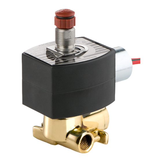
Series 8317 valves are 3-way direct-acting with quick exhaust
solenoid valves designed for air or inert gas service. Valve bodies are
made of rugged brass or stainless steel. The valves may be provided
with a low power or intrinsically safe solenoid.
OPERATION
Universal Pressure at 2 (Normally Closed Operation)
Solenoid De-energized: Pressure at 2 is closed, flow is from cylinder
1 to main exhaust 4. Pilot exhaust 3 is open.
Solenoid Energized: Flow is from pressure 2 to cylinder 1. Main
exhaust 4 and pilot exhaust 3 are closed.
Universal Pressure at 3 (Normally Open Operation)
Solenoid De-energized: Flow is is from pressure 3 cylinder 1. Main
exhaust 4 and pilot exhaust 2 are closed.
Solenoid Energized: Pressure at 3 is closed, flow is from cylinder 1 to
main exhaust 4. Pilot exhaust 2 is open.
Note: This construction is interchangeable from Pressure at 2 to
Pressure at 3 (or vice versa) by changing the piping.
IMPORTANT: Minimum operating pressure differential 5 psi.
Flow Diagrams
Universal - Pressure at 2
3
2
1
4
De-energized
3
Main
Exh.
2
1
4
Energized
INSTALLATION
Check nameplate for correct catalog number, pressure, voltage,
frequency, and service. Never apply incompatible fluids or exceed
pressure rating of the valve. Installation and valve maintenance to be
performed by qualified personnel.
Temperature Limitations
Fluid and ambient temperature range: -4_ F to +140_F.
Future Service Considerations
Provision should be made for performing seat leakage, external
leakage, and operational tests on the valve with a nonhazardous,
noncombustible fluid after disassembly and reassembly.
Positioning
Valve may be mounted in any position.
e
ASCO Valves
1/4I NPT - AIR OR INERT GAS SERVICE
Universal - Pressure at 3
3
2
1
4
De-energized
3
Pilot
Exh.
2
1
4
Energized
MCMXCIII All Rights Reserved.
Mounting
For mounting valve body refer to Figure 1.
.750
19
1.500
38
Figure 1. Dimensions for mounting valve body.
Piping
There are two exhaust flows in the exhaust mode. The pilot exhaust
may be connected to the main exhaust if the air or inert gas cannot be
exhausted directly to the atmosphere. For universal valves with
pressure at 2 (normally closed operation) the pilot exhaust is at 3 and
may be connected to main exhaust 4. For universal valves with
pressure at 3 (normally open operation) the pilot exhaust is at 2 and
may be connected to main exhaust 4. Connect piping or tubing to
valve according to markings on valve body. Refer to flow diagrams in
OPERATION section.
CAUTION: To avoid damage or accidental disengagement of
cartridge assembly from valve body, hold cartridge assembly
securely by wrenching flats when installing or removing piping at
Port 3.
Apply pipe compound sparingly to male pipe threads only. If applied
to valve threads, the compound may enter the valve and cause
operational difficulty. Avoid pipe strain by properly supporting and
aligning piping. When tightening the pipe, do not use valve or
solenoid as a lever. Locate wrenches applied to valve body or piping
as close as possible to connection point.
To insure proper operation of the valve, the pressure and exhaust lines
must be full area without restriction. A minimum differential
pressure (5 psi), as stamped on the nameplate, must be maintained
between pressure and exhaust at the moment of shifting. Air
reservoirs must have adequate capacity to maintain this minimum
pressure during shifting. To check pressure during shifting, install a
pressure gauge in the pressure piping as close to the valve as possible.
IMPORTANT: These solenoid valves are intended for use on clean
dry air or inert gas, filtered to 50 micrometres or better. The dew
point of the media should be at least 10_ C (18_ F) below the
minimum temperature to which any portion of the clean air/inert
gas system could be exposed to prevent freezing. If lubricated air is
used, the lubricants must be compatible with Buna N elastomers.
Diester oils may cause operational problems. Instrument air in
compliance with ANSI/ISA Standard S7.3-1975 (R1981) exceeds
the above requirements and is, therefore, an acceptable media for
these valves.
Printed in U.S.A.
50-60 Hanover Road, Florham Park, New Jersey 07932
SERIES
8317
Form No.V6860R1
.200
5
Page 1 of 2
Advertisement
Table of Contents

Related Manuals for Asco 8317 Series


Summary of Contents for Asco 8317 Series
- Page 1 Positioning Valve may be mounted in any position. these valves. Page 1 of 2 MCMXCIII All Rights Reserved. Printed in U.S.A. ASCO Valves 50-60 Hanover Road, Florham Park, New Jersey 07932...
- Page 2 Parts marked with an asterisk (*) in the exploded view are supplied in depressurize valve, and vent fluid to a safe area before Rebuild Kits. When Ordering Rebuild Kits for ASCO valves, order servicing the valve. the Rebuild Kit number stamped on the valve nameplate. If the...
Need help?
Do you have a question about the 8317 Series and is the answer not in the manual?
Questions and answers
Does this solenoid valve come with flying leads?