Table of Contents
Advertisement
Quick Links
Advertisement
Table of Contents

Related Manuals for Colorjet PoloTurbo


Summary of Contents for Colorjet PoloTurbo
- Page 2 Disclaimer The information and instructions provided in this user manual have been checked for accuracy, uniqueness, and reliability. ColorJet group reserves all the rights to modify and revise this manual as per the company requirements without any prior notice. “No part of this document shall be reproduced or used by externals without prior permission of the ColorJet group”.
-
Page 3: Table Of Contents
Table of Contents 1. About Document ............................3 Purpose ................................ 3 Intended Audience ............................3 2. Printer Accessories ............................3 3. Printer Overview ............................4 Back View of the Printer ..........................5 Control Panel Details............................ 6 4. Getting Familiar with Printer Manager Interface ..................7 5. - Page 4 Head Purging .............................. 31 Head Spraying ............................32 9. Shutdown & Capping the Print Head ......................33 10. Maintenance ............................34 Print Head Maintenance ..........................34 Daily maintenance ............................. 34 11. Troubleshooting ............................35 12. Error Code Specifications ......................... 37 POLO TURBO Page | 2...
-
Page 5: About Document
1. About Document Purpose The purpose of this document is to guide and educate the targeted audience about the Printer and its Printer Manager software so that they can easily and effectively handle as well as use it as per their requirements. -
Page 6: Printer Overview
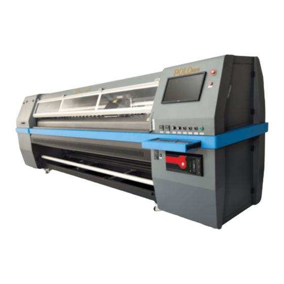
3. Printer Overview Front View of the Printer The Front View of the printer is shown as below: Fig 1: Displaying the Front View Table 1: Different Parts of the Printer 1. Front Glass Door 2. LCD Monitor 3. Emergency Button 4. -
Page 7: Back View Of The Printer
Back View of the Printer The Back View of the printer is shown as below: Fig 2: Displaying the Back View Table 2: Different Parts of the Printer 15. Waste Bottle Tank 16. Main Ink Tank 17. Pre Heater 18. Pinching Roller / Vinyl Supply Roller 19. -
Page 8: Control Panel Details
Control Panel Details The Control Panel Screen is shown as below: Emergency Switch Power ON/OFF Buttons LCD Monitor Post Heater Pre Heater IR Heater Auto/Manual Lever Supply Auto/Manual IR Heater Keyboard Supply Rev/Fwd Bed Vacuum Take-up Rev/Fwd Take-up Regulator Take-up ON/OFF Computer System Slot Fig 3: Displaying the Control Panel The description of different parts of the machine is given as below:... -
Page 9: Getting Familiar With Printer Manager Interface
4. Getting Familiar with Printer Manager Interface The User Interface of the Printer Manager software is shown as below: Window Controls Quick Access Toolbar System Status Print Parameters Job Preview Job Information Job List Error Information Fig 4: Displaying the User Manual of Printer Manager Main Menu The description of the Printer Manager window is given as below: •... -
Page 10: Main Menu Options
5. Main Menu Options The Main Menu options are shown in the image below: Fig 5: The Main Menu Options Setting Menu The Setting menu options are shown in the image below: Fig 6: The Setting Menu Options • Save: Using this option, you can save the default settings of the machine. When you save the settings, an xml file will be created for further references. - Page 11 The Setting window with the Printer tab is shown in the below image: Fig 7: Displaying the Setting Window Describing the different sections of the Setting window, as given below: • Print setting o Auto skip white: Enable to auto skip the white space in the image during printing. o Step Time: Set time interval of the feed motor during printing.
- Page 12 • Spray setting • Auto Spray: Set the duration (number of passes) for auto spraying. • Spray Period: Define the duration for spraying (set as 180). If the duration increased, spray frequency gets decreased. • Print Pre-spray Time: This is the duration of spray before start of print. •...
-
Page 13: Tools Menu
The Calibration tab is shown in the image below: Fig 10: Displaying the Calibration Wizard Tools Menu The Tools menu options are shown in the image below: Fig 11: The Tools Menu Option • Update: This option enables to apply latest changes and updates in the machine. This option supports .dat file format. -
Page 14: Help Menu
• Real Setting: This option enables to check and reset the temperature as well as voltage of each Print Head. • Wave Form Setting: This option helps in controlling and setting the wave form of the printer with respect to ink, Print Head type, and speed. •... -
Page 15: Getting Ready For Printing
6. Getting Ready for Printing Switch ON Procedure Follow these steps to switch ON the printer: Step 1: Check the Waste Bottle. Step 2: Check Ink Level. Step 3: Maintain the room temperature. Step 4: Move the carriage manually away from the home position. Step 5: Switch ON the printer from the main power or board. - Page 16 Step 4: Pull the media out in front of the machine. Step 5: Holding the media firmly and push down the Media Lever. Step 6: Turn on the Supply Auto/Supply switch in auto mode and carefully observe the direction of media either reverse or forward.
- Page 17 Step 10: Turn on the Take Up System and observe the media direction (either reverse or forward), as shown below: Fig 15: Enabling the Take-Up System Step 11: Move the media forward so that it rolls easily over the Core. Now, the media gets loaded.
- Page 18 The media loading path of the machine is shown with help of line diagram: Fig 16: Displaying the Media Loading Path POLO TURBO Page | 16...
-
Page 19: Ink Filling
Ink Filling Please use the recommended ink in the printer for high printing quality and long life of print and Print Head. Follow these steps to fill ink in the printer Step 1: Open the left door of the printer to find out main tanks. Step 2: Fill recommended ink in main ink tank (as per the color sticker) as per the requirement, as shown below: Fig 17: Displaying the Ink Tank... -
Page 20: Printing
7. Printing Nozzle Testing Before starting with calibration tests, the Print Heads should be checked for blockage. Each Print Head has multiple tiny nozzles through which ink drops emerge and get deposited onto the print medium. Any nozzle blockage can compromise the print quality by forming discolored horizontal streaks or bands. The good and bad nozzle test results are shown in the image below: Fig 19: Good and Bad Nozzle Test Result To check the nozzle, click on the Check Nozzle icon available on the Quick Access Toolbar, as shown... -
Page 21: Print Head Calibration
Print Head Calibration The Print Head calibration is categorized into the following types: • Mechanical Check: Includes Vertical Check and Angle Check • Software Calibration: Includes Horizontal Calibration and Step Calibration Note: Mechanical checks are only performed by the Service Engineer. Calibration Wizard Print Heads should be calibrated to ensure good printing quality. - Page 22 This should bring up the calibration wizard which is shown below: Fig 22: Displaying the Calibration Wizard When you press the Next button, we redirect to the software calibration screen, as shown in the below images: Fig 23: Displaying the Printer Calibration Options Note: Base Step value should be 25000.
-
Page 23: Horizontal Calibration
Horizontal Calibration Horizontal Calibration checks the bi-directional, left, and right alignment and corrects it by adding or subtracting the correction value from the default set value. It has to be performed for each print mode, whichever is required. Let’s discuss each type of horizontal test one by one. Bi-direction Calibration Bi-directional calibration is performed to achieve dot placement accuracy between the “Left to Right”... - Page 24 Left to Right and Right to Left Calibrations Left to Right Calibration is performed to achieve dot placement accuracy of all colors (Black, Cyan, and Yellow) with respect to Magenta during the carriage’s left to right print sweep. Similarly, Right to Left calibration is used to achieve dot placement accuracy during the carriage’s right to left sweep.
-
Page 25: Step Calibration
Step Calibration The printer step calibration is performed to verify and correct media feeding. The printer prints a complete image pass by pass. A pass is the horizontal carriage sweep perpendicular to the media movement. After each pass the printer moves the media forward for the next pass. This movement of media is called a step. -
Page 26: Setting Print Origin
The Step Calibration and its parameters are shown in the image below: Fig 27: The Step Calibration Parameters Follow these steps to perform step calibration: Step 1: Select the desired pass from the list and click on the Print button (Refer to Fig 27). Step 2: Feed the correction value in the Revise field (the correction value up to two decimal places) (Refer to Fig 27). -
Page 27: Setting Print Parameters
On clicking the Set print origin icon, the current position of the carriage gets updated in the Origin X text box, as shown below: Fig 30: Displaying the Origin Value Now, the printing origin gets set. Additionally, you can also enter the print origin value manually in the Origin X field under the Print Parameter section. - Page 28 Step 3: Click on the Open button to add the file into the Job List area, as shown below: Fig 33: Adding the Job Now, the selected image appears in the Job List area, as shown below: Fig 34: Displaying the Added Job and Their Details POLO TURBO Page | 26...
-
Page 29: Editing Job
Once a file has been added its information such as file path, size, resolution, and number of passes can be viewed in the Job Information area. User can also add a job simply by right clicking on the Job List area and selecting the Add Job option from the context menu, as shown below: Fig 35: Displaying the Context Menu On selecting the Add Job option, the Open window appears and follow the above-mentioned steps to add... -
Page 30: Ripping And Printing
Copies: Feeding any number of copies will repeat the prints in Y direction. Careful, the Print will stop and restart after each copy. Foot note: You can add footnote printing with each printed image. Parameters required can be selected. Step 5: After making the desired changes, click on the OK button to apply the settings, as shown below: Fig 37: Displaying the Edit Job Form Window Similarly, you can click on any other option and its related options get enabled in the right pane of the Edit Job form. -
Page 31: Pausing And Canceling Printing
After issuing the Print command, the printing gets started and its progress details displays in the Job Information area, as shown below: Fig 39: Displaying the Printing Details Pausing and Canceling Printing If you find any defect during the printing process, you can immediately pause or cancel the current printing job using the Pause or resume and Abort Job buttons available on the Quick Access Toolbar as shown below: Fig 40: Issuing the Pause or resume Command... -
Page 32: Head Cleaning
8. Head Cleaning Print Head is a delicate part which needs to be cleaned as per the recommended methods to have long life and to ensure consistent print quality. Below sections give recommended steps to clean the Print Heads. Head Blotting Head blotting refers to the process in which the head surface area is cleaned with the help of tissue paper or cloth. -
Page 33: Head Purging
Note: Please strictly follow the below mentioned instructions: • Avoid using the same tissue paper to wipe the Print Head. • Blotting with dry and inferior quality tissue paper will damage the nozzle film by making scars (see image in next page). •... -
Page 34: Head Spraying
Note: If nozzles are found blocked even after normal purging, then try the powerful purging (“P” switch in purging board has to be kept pressed for few seconds and then required color switch has to be pressed). Head Spraying Head spraying clears the mixing of colors during blotting, may also clear few dry nozzles. When heads are sprayed, all the nozzles are actuated at a high rate which helps in opening up few dry nozzles of the printer. -
Page 35: Shutdown & Capping The Print Head
9. Shutdown & Capping the Print Head Capping refers to the process of protecting the Print Head to become dry. Perform the following steps to cap the Print Head: Step 1: Clean the capping area. Step 2: Fill the capping pads with solvent, as shown below: Capping Slots Fig 44: Displaying the Capping Station Step 3: Switch off the printer. -
Page 36: Maintenance
10. Maintenance Print Head Maintenance Print Head is an important and delicate part of the printer. Thus, it must be handled with care to ensure the long life of the Print Heads. For Print Head maintenance, the following instructions should be taken care: •... -
Page 37: Troubleshooting
11. Troubleshooting PRINTER NOT INITIALIZING • Encoder scale is having ink stains (print shows vertical color bands) • Encoder sensor is not cleaned • Emergency button is pressed PRINTER MANAGER NOT SHOWING “READY” • USB cable is not connected to the computer or loose •... - Page 38 • Check the ink and air pipe for any cuts or loose connection TAKE – UP NOT WORKING • Take-up switch is not ON • Take-up regulator is in OFF position MEDIA SUPPLY NOT WORKING • Supply switch is not ON •...
-
Page 39: Error Code Specifications
12. Error Code Specifications Table 3: The Error Code and their Description Error Code Error Description Remedial Action 04020008 Wrong input or forbidden character in the Re-input the Correct Time Limit Time Limit Password field. Password Field 04020009 Illegal Time Limit Password. Re-input the Correct Time Limit Password Field 0402000A... - Page 41 For Any Query Please Contact Us www.colorjetgroup.com Call us on +91-120-4548195 Email on info@colorjetgroup.com For Ink Enquiry:- sales@colorjetgroup.com For Support:- support@colorjetgroup.com...
Need help?
Do you have a question about the PoloTurbo and is the answer not in the manual?
Questions and answers