MINN KOTA FORTREX User Manual
Bow-mount trolling motor
Hide thumbs
Also See for FORTREX:
- Owner's manual (62 pages) ,
- Installation instructions manual (53 pages) ,
- User manual (42 pages)
Table of Contents
Advertisement
Advertisement
Table of Contents

Related Manuals for MINN KOTA FORTREX


Summary of Contents for MINN KOTA FORTREX
- Page 1 FORTREX ® BOW-MOUNT TROLLING MOTOR USER MANUAL...
- Page 2 REMEMBER TO KEEP YOUR RECEIPT AND IMMEDIATELY REGISTER YOUR TROLLING MOTOR. NOTE: Do not return your Minn Kota motor to your retailer. Your retailer is not authorized to repair or replace this unit. You may obtain service by: calling Minn Kota; returning your motor to the Minn Kota Factory Service Center; sending or taking your motor to any Minn Kota authorized service center.
-
Page 3: Table Of Contents
TABLE OF CONTENTS Two-Year Limited Warranty Features Mount Installation Battery & Wiring Installation 10-11 Boat Rigging & Product Installation Conductor Gauge and Circuit Breaker Sizing Table Selecting the Correct Batteries How to Connect Batteries Motor Wiring Diagram Using & Adjusting The Motor 13-15 Stowing &... -
Page 4: Two-Year Limited Warranty
MINN KOTA LIMITED LIFETIME WARRANTY ON COMPOSITE SHAFT JOME warrants to the original retail purchaser only that the composite shaft of the purchaser’s Minn Kota trolling motor will be materially free from defects in materials and workmanship appearing within the original purchaser’s lifetime. JOME will provide a new composite shaft, free of charge, to replace any composite shaft found by JOME to be defective during the term of this warranty. -
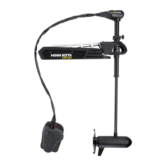
Page 5: Features
FEATURES Mono-Arm Design Directional Indicator Depth Collar Knob BowGuard 360° ® Breakaway Protection Lift-Assist Lifetime Warranty Momentary On Button Flexible Composite Shaft Constant On Switch Speed Control Cool Quiet Power Motor Heel Block High-Impact Composite Material Propeller Specifications subject to change without notice. This diagram is for reference only and may differ from your actual motor. -
Page 6: Mount Installation
MOUNT INSTALLATION TOOLS AND RESOURCES REQUIRED: • Phillips Screw Driver • 1/4” Allen Wrench • Drill • 9/32” Drill Bit • 7/16” Box End Wrench • A second person to help with the installation ASSEMBLY OF MOTOR TO MOUNT 1. Place the mount on an elevated surface such as a workbench or tailgate of pickup. 2. - Page 7 MOUNT INSTALLATION INSTALLATION OF THE BOW-MOUNT We recommend that you have another person help with this procedure. 1. For installation, DO NOT REMOVE THE SHAFT/MOTOR FROM THE BOWGUARD. The Bowguard spring is under tension and must always remain secured. 2. Place the mount, with the motor in the fully stowed (fl at) position, on the deck of the boat: •...
- Page 8 MOUNT INSTALLATION INSTALLING THE BOWMOUNT STABILIZER 1. Place motor in the stowed position. 2. Unthread the composite rod from the bracket and attach bracket to the bottom of the Bowguard using the 5/16” cap screws and nuts. The nuts fi t into pocket on the inside of the Bowguard behind the spring. NOTE: The bracket can be installed on the left or right side of the Bowguard.
- Page 9 MOUNT INSTALLATION REMOVAL OF THE BOWGUARD WARNING: The gas assist lift mechanism in this unit is under HIGH SPRING PRESSURE when the motor is in the deployed position. DO NOT remove the Bowguard assembly from the mount without disconnecting one end of the gas spring. Failure to do this can create a condition where accidental pulling of the rope may cause the mount to spring open rapidly, striking anyone or anything in the direct path.
-
Page 10: Battery & Wiring Installation
CAUTION: These guidelines apply to general rigging to support your Minn Kota motor. Powering multiple motors or additional electrical devices from the same power circuit may impact the recommended conductor gauge and circuit breaker size. If you are using wire longer than that provided with your unit, follow the conductor gauge and circuit breaker sizing table below. -
Page 11: Selecting The Correct Batteries
Breaker Sizing Table” in the previous section to fi nd the appropriate circuit breaker or fuse for your motor. For motors requiring a 60-amp breaker, the Minn Kota MKR-19 60-amp circuit breaker is recommended. CONNECTING THE BATTERIES IN SERIES (IF REQUIRED FOR YOUR MOTOR) -
Page 12: Motor Wiring Diagram
MOTOR WIRING DIAGRAM NOTE: This is a universal, multi-voltage diagram. Double-check your motor's voltage for proper connections. Over-Current Protection Devices not shown in this illustration. SPEED ADJUSTMENT SWITCH OPTIONAL BROWN WIRE FOR MOTORS WITH 70 LBS THRUST AND HIGHER. SEE BOAT WIRING DIAGRAM. BLK/RED M+ BLACK M- FUSE*... -
Page 13: Stowing & Deploying The Motor
USING AND ADJUSTING THE MOTOR STOWING AND DEPLOYING THE MOTOR WARNING: When raising or lowering the motor, keep fi ngers clear of all hinge and pivot points and all moving parts. MOUNT FEATURES • The motor mount is designed to fold back and lock the motor fl at on the deck when not in use and to provide secure stowage for transport. -
Page 14: Using & Adjusting The Motor
USING & ADJUSTING THE MOTOR ADJUSTING THE DEPTH OF THE MOTOR Depth Adjustment Knob The propeller tip must be submerged at least 12” to avoid churning Depth Adjustment Knob or agitation of surface water. Outer Shaft 1. With the motor deployed, fi rmly grasp the outer shaft or control Outer Shaft head and hold it steady. -
Page 15: Controlling Speed And Steering With The Foot Pedal
USING & ADJUSTING THE MOTOR CONTROLLING SPEED & STEERING WITH THE FOOT PEDAL Most controls on the foot pedal are easy to operate by either foot or hand: Toe End Speed Knob Momentary On Button Directional Directional Indicator Indicator Heel End Constant On Switch TO ADJUST MOTOR SPEED Turn the speed knob clockwise to increase speed and counter-clockwise to decrease speed. -
Page 16: Service & Maintenance
SERVICE & MAINTENANCE PROPELLER REPLACEMENT TOOLS AND RESOURCES REQUIRED: Propeller • Box End Wrench Slot End - 1/2” for motors with 70 lbs thrust or lower. - 9/16” for motors with 80 lbs thrust or higher. Prop Nut Washer • Screwdriver (optional) CAUTION: Disconnect the motor from the battery before beginning any prop work or... -
Page 17: Troubleshooting & Repair
TROUBLESHOOTING & REPAIR 1. Motor fails to run or lacks power: • Check battery connections for proper polarity. • Make sure terminals are clean and corrosion free. Use fi ne sandpaper or emery cloth to clean terminals. • Check battery water level. Add water if needed. 2. -
Page 18: Environmental Compliance Statements
Minn Kota motors are not subject to the disposal regulations EAG-VO (electric devices directive) that implements the WEEE directive. Nevertheless never dispose of your Minn Kota motor in a garbage bin but at the proper place of collection of your local town council. -
Page 19: Parts Diagram
FORTREX 80 80 LBS THRUST - 24 VOLT - 52”/62” SHAFT This page provides Minn Kota® WEEE compliance disassembly instructions. For more information about where you should dispose of your waste equipment for recycling and recovery and/or your European Union member state require- ments, please contact your dealer or distributor from which your product was purchased. -
Page 20: Parts List
PARTS LIST FORTREX 80 80 LBS THRUST - 24 VOLT - 52”/62” SHAFT PART PART ITEM DESCRIPTION ITEM DESCRIPTION NUMBER NUMBER 2316217 24V MOTOR 52” FW 2265430 CABLE JACKET, 5’ 2316219 24V MOTOR US2 62” 2261220 WIRE HARNESS, MAX 2326241 24V MOTOR US2 52”... - Page 21 PARTS LIST FORTREX 80 80 LBS THRUST - 24 VOLT - 52”/62” SHAFT PART PART ITEM DESCRIPTION ITEM DESCRIPTION NUMBER NUMBER 2262632 PIN, SPRING 1/4 X 5/8 2261732 WASHER 8, NYLON 2266000 BEARING, BALL, STEEL 2373450 SCREW 8-18 X 3/8...
- Page 22 Stop buying new batteries and start taking care of the ones you’ve got. Many chargers can actually damage your battery over time – creating shorter run times and shorter overall life. Digitally controlled Minn Kota chargers are designed to provide the fastest charge that protect and extend battery life.
Need help?
Do you have a question about the FORTREX and is the answer not in the manual?
Questions and answers