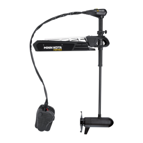
MINN KOTA FORTREX Owner's Manual
Bow-mount trolling motor
Hide thumbs
Also See for FORTREX:
- Owner's manual (62 pages) ,
- Installation instructions manual (53 pages) ,
- User manual (22 pages)
Table of Contents
Advertisement
Advertisement
Table of Contents
Troubleshooting

Related Manuals for MINN KOTA FORTREX


Summary of Contents for MINN KOTA FORTREX
- Page 1 FORTREX ® BOW-MOUNT TROLLING MOTOR Owner's Manual...
- Page 2 THANK YOU Thank you for choosing Minn Kota. We believe that you should spend more time fishing and less time positioning your boat. That’s why we build the smartest, toughest, most intuitive trolling motors on the water. Every aspect of a Minn Kota trolling motor is thought out and rethought until it’s good enough to bear our name.
-
Page 3: Table Of Contents
TABLE OF CONTENTS SAFETY CONSIDERATIONS ....................4 WARRANTY ........................5 KNOW YOUR BOAT ......................6 FEATURES ........................7 INSTALLATION ......................... 8 Assembly of Motor to Mount ..................9 Installing the Bowguard..................10 Installing the Gas Spring Pin .................. 13 Placing the Bow-mount Stabilizer ................14 Mounting the Foot Pedal .................. -
Page 4: Safety Considerations
WARNING You are responsible for the safe and prudent operation of your vessel. We have designed your Minn Kota product to be an accurate and reliable tool that will enhance boat operation and improve your ability to catch fish. This product does not relieve you from the responsibility for safe operation of your boat. -
Page 5: Warranty
Products purchased outside of the U.S. must be returned prepaid with proof of purchase (including the date of purchase and serial number) to any Authorized Minn Kota Service Center in the country of purchase. -
Page 6: Know Your Boat
KNOW YOUR BOAT Port Starboard Inboard Outboard Keel Port Starboard Gunwale Transom Stern Gunwale Stern Hull 6 | minnkotamotors.com ©2018 Johnson Outdoors Marine Electronics, Inc. -
Page 7: Features
FEATURES Mono-Arm Directional Indicator Design Depth Collar Knob BowGuard 360° ® Breakaway Protection Lift-Assist Lifetime Warranty Momentary On Button Flexible Composite Shaft Constant On Switch Speed Control Cool Quiet Power Motor Heel Block High-Impact Composite Material Propeller NOTICE: Specifications subject to change without notice. This diagram is for reference only and may differ from your actual motor. -
Page 8: Installation
INSTALLING THE FORTREX Your new Fortrex comes with everything you’ll need to directly install it to the boat. This motor can be directly mounted to the boat or coupled with a Minn Kota quick release bracket for ease of mounting and removal. For installation with a quick release bracket, refer to the installation instructions provided with the bracket. -
Page 9: Assembly Of Motor To Mount
ASSEMBLY OF MOTOR TO MOUNT MOUNTING CONSIDERATIONS It is recommended that the motor be mounted as close to the keel or centerline of the boat as possible. Make sure the area under the mounting location is clear to drill holes and install View accessories nuts and washers. -
Page 10: Installing The Bowguard
INSTALLING THE BOWGUARD Align the Keyways on the inside of the Bowguard Pull Grip and Rope with the End Links on the Mount. Lower the motor Allen Screw assembly straight down until seated. Lock Washer Install the 5/16” Allen Screw and the Lock Washer and tighten to 10-12 ft/lbs. - Page 11 INSTALLING THE BOWGUARD ITEM(S) NEEDED #20 x 1 Review the mounting considerations at the beginning of the Installation section for proper placement. Place the Mount as close to the centerline or keel of the boat as possible, with the motor in the deployed Mount position, on the deck of the boat.
- Page 12 INSTALLING THE BOWGUARD Check the placement with the motor in the deployed position. When the motor is in the deployed position, make sure that the Shaft is 1-1/2" out past the Gunwale of the boat. The lower unit, when stowed and deployed must not encounter any obstructions.
-
Page 13: Installing The Gas Spring Pin
INDEXING THE MOTOR ITEM(S) NEEDED #6 x 6 #5 x 6 #4 x 6 Put a 1/4-20 x 2 1/2" Screw (Item #4) in each of the drilled locations. The Screw should pass through the Screw Mount Plate and the boat deck. Place a Flat Washer (Item #5) and then a Nylock Nut (Item #6) at the end of each screw as shown and secure. -
Page 14: Placing The Bow-Mount Stabilizer
The Bow-Mount Stabilizer is not required or Bowguard and reduce bouncing when the motor is stowed and included on the 80lb 45” Fortrex. transported. Attention to detail is needed for successful installation of the stabilizer. We recommend to have the stabilizer bracket installed by a qualified marine installer. - Page 15 Bowguard behind the spring. Secure with a 1/4” Allen Wrench. Tighten to 10 ft lb. NOTICE: The two Lock Washers (Item #16) are not used when installing on the Fortrex. minnkotamotors.com | 15 ©2018 Johnson Outdoors Marine Electronics, Inc.
- Page 16 PLACING THE BOW-MOUNT STABILIzER Measure the proper length of the Aluminum Rod by Stabilizer standing it, with the threaded end down, onto the Bracket deck surface so that it sits vertically right next to the Stabilizer Bracket. 3/4" Mark the Aluminum Rod with a pencil or marker 3/4" past the top of the Stabilizer Bracket.
-
Page 17: Mounting The Foot Pedal
MOUNTING THE FOOT PEDAL Once in the correct position, tighten the Jam Nut Top Bumper upwards against the Stabilizer Bracket. This will Stabilizer prevent the Aluminum Rod from turning. Bracket Install the Top Bumper if there are threads exposed Jam Nut on the Aluminum Rod above the Stabilizer Bracket. -
Page 18: Identifying Trolling Motor Features By Their Associated Cables
IDENTIFYING TROLLING MOTOR FEATURES BY THEIR ASSOCIATED CABLES IDENTIFYING TROLLING MOTOR FEATURES BY THEIR ASSOCIATED CABLES Your trolling motor may be pre-installed with Built-In MEGA Down Pedal Control Sleeve Imaging OR Universal Sonar. These features require cables to be Connection Assembly from Control Head Cable connected to an output device. - Page 19 ROUTING CONNECTION CABLES Identify where the Built-in MEGA Down Imaging or Universal Sonar Cable needs to be connected and route along an established routing system in your boat. Use cable ties to loosely secure cables if needed. Power Cables NOTICE: After the cable(s) exit(s) the Foot Foot Pedal Pedal, it should be routed through an established...
-
Page 20: Feature Overview And Connecting The Cables
Built-In MEGA Down Imaging delivers nearly 3X the output of standard Side Imaging®, and takes fishfinding into the megahertz frequency for the very first time. The Minn Kota flagship families of trolling motors, including Ultrex, Ulterra, Terrova, and Fortrex, now include Built-In MEGA Down Imaging sonar, the clearest imaging available only from Humminbird. - Page 21 FEATURE OVERVIEW AND CONNECTING THE CABLES When installing with a Solix, the Built-In MEGA Humminbird Solix Fish Finder Down Imaging cable can be plugged directly into the Solix fish finder. Plug the Built-in MEGA Down Imaging cable into the corresponding connection on the Solix fish finder.
-
Page 22: Universal Sonar
FEATURE OVERVIEW AND CONNECTING THE CABLES Universal Sonar Your trolling motor may be pre-installed with a Universal Sonar transducer system. Universal Sonar is a 2D sonar transducer with a temperature sensor that is integrated into the lower unit of the trolling motor. It has an operating frequency of 83/200 kHz. Connecting this transducer to a compatible fish finder gives you a 2D sonar view of what is happening directly below your trolling motor. - Page 23 If the cable length does not reach the desired fish finder installation location, a 14.5’ extension cable is Four Pin Connector available to purchase. Minn Kota recommends using the MKR-US2-11. Take the Universal Sonar Extension Cable, if needed, Locking Collar and attach it to the Universal Sonar Cable exiting the Foot Pedal.
-
Page 24: Battery & Wiring Installation
CAUTION These guidelines apply to general rigging to support your Minn Kota motor. Powering multiple motors or additional electrical devices from the same power circuit may impact the recommended conductor gauge and circuit breaker size. If you are using wire longer than that provided with your unit, follow the conductor gauge and circuit breaker sizing table below. -
Page 25: Selecting The Correct The Batteries
Review your charger’s manual carefully or consult the manufacturer prior to use to ensure your charger is compatible. Minn Kota recommends using Minn Kota brand chargers to recharge the batteries connected to your Minn Kota trolling motor, as they have been engineered to work with motors that include a bonding wire. -
Page 26: Connecting The Batteries In Series
CONNECTING THE BATTERIES IN SERIES positivevoltage into the “ground” of that accessory, which can cause excess corrosion. Any damage caused by incorrect connections between battery systems will not be covered under warranty. Automatic Jump Start Systems and Selector Switches Automatic jump start systems and selector switches tie the negatives of the connected batteries together. Connecting these systems to the “High Side”... - Page 27 CONNECTING THE BATTERIES IN SERIES 36 Volt Systems Three 12 volt batteries are required. The batteries must be wired in series, only as directed in wiring diagram, to provide 36 volts. Make sure that the motor is switched +36 Volts to trolling motor off (speed selector on “0”).
-
Page 28: Motor Wiring Diagram
MOTOR WIRING DIAGRAM FORTREX The following Motor Wiring Diagram applies to all Fortrex Foot Control models that do not come preinstalled with Built-in MEGA Down Imaging. Universal Sonar is an optional feature that may come factory installed. Control Head Indicator Light... - Page 29 MOTOR WIRING DIAGRAM FORTREX The following Motor Wiring Diagram applies to all Fortrex Foot Control models that come preinstalled with Built-in MEGA Down Imaging. Control Head Indicator Light Fuse Orange Brown Ground Black M- Built-in MEGA Brown Down Imaging Black M-...
-
Page 30: Using & Adjusting The Motor
Be alert for unexpected boat movement when operating the temperatures, which can be increased by an excessively hot Fortrex. The boat may encounter sharp turns and jolts if the operating environment. Use care when handling the Control steering is changed sharply or if broad changes in speed are Head and Foot Pedal to avoid burns or injuries from excessive made while operating. -
Page 31: Stowing And Deploying The Motor
USING & ADJUSTING THE MOTOR STOWING AND DEPLOYING THE MOTOR WARNING When stowing or deploying the motor, keep fingers clear of all hinge and pivot points and all moving parts. Practice proper ergonomics when stowing and deploying the motor to prevent injury. WARNING Moving the motor creates a variety of pinch points. -
Page 32: Motor Adjustments
ADJUSTING THE LOWER UNIT FOR A SECURE STOW MOTOR ADJUSTMENTS MOTOR ADJUSTMENTS Adjusting the Lower Unit for a Secure Stow When the Motor is stowed, the Lower Unit should rest on the Mount Ramps just inside the Motor Rest on the Motor Mount. It is recommended to secure the motor using the following instructions to avoid damage to the motor and shaft from vibrations during transport. -
Page 33: Adjusting The Depth Of The Motor
ADJUSTING THE DEPTH OF THE MOTOR With the motor in the deployed position, firmly grasp the motor Shaft above the Bowguard. Depth Adjustment Locate the Depth Adjustment Knob on the Shaft. Knob Loosen the Depth Adjustment Knob, while holding the Shaft in place, until the Shaft slides freely. Raise or lower the motor to the desired depth. -
Page 34: Installing An External Transducer
INSTALLING AN EXTERNAL TRANSDUCER INSTALLING AN EXTERNAL TRANSDUCER An external transducer is not included with your trolling motor. An external transducer can be installed onto motors that have Universal Sonar or motors that do not have a built in transducer. For more information on Universal Sonar, please visit minnkotamotors.com. Installing an external transducer is not recommended for motors with Built-in MEGA Down Imaging. -
Page 35: Using The Foot Pedal
USING THE FOOT PEDAL CONTROLLING SPEED & STEERING WITH THE FOOT PEDAL Most controls on the Foot Pedal are easy to operate by either foot or hand. Speed Knob Toe End Directional Indicator Momentary On Heel End Button Constant On Switch To Adjust Motor Speed Turn the speed knob clockwise to increase speed and counter-clockwise to decrease speed. -
Page 36: Foot Pedal Adjustments
ADJUSTING THE STEERING CABLE CAUTION Route the Foot Pedal Cable neatly to minimize tripping hazards. Practice proper ergonomics when operating the Foot Pedal to avoid fatigue and prevent injury. FOOT PEDAL ADJUSTMENTS Adjusting the Steering Cable The steering cable tension is pre-set at the factory but, through normal use, may need occasional adjustment. Adjust the tension of the cables by turning the cable Stainless Steel Cable Cable Tension Adjustment Screw... -
Page 37: Service & Maintenance
SERVICE & MAINTENANCE PROPELLER REPLACEMENT TOOLS AND RESOURCES REQUIRED • 9/16” Open End Wrench • Flat Blade Screwdriver INSTALLATION Disconnect the motor from all sources of power prior to changing the propeller. Drive Pin Armature Shaft Hold the propeller and loosen the Prop Nut with a pliers or a wrench. -
Page 38: Removal Of The Bowguard
SERVICE & MAINTENANCE REMOVAL OF THE BOWGUARD TOOLS AND RESOURCES REQUIRED (2) #3 Phillips screwdrivers Torque Wrench 1/4” Allen Wrench Needle Nose Pliers INSTALLATION Disconnect the Gas Spring WARNING Gas Spring Cylinder Yoke Moving parts can cut or crush. The gas assist lift mechanism is under pressure. -
Page 39: Remove Motor From Mount
SERVICE & MAINTENANCE Once the screws are removed, the pin and spacers Outer Arm can be removed from the Upper Cylinder. Now it is safe to remove the motor from the bow mount when the motor is in the deployed position. Gas Spring Cylinder Outer Arm Remove Motor From Mount... -
Page 40: General Maintenance
SERVICE & MAINTENANCE GENERAL MAINTENANCE • After use, the entire motor should be rinsed with freshwater. This series of motors is not equipped for saltwater exposure. • The composite shaft requires periodic cleaning and lubrication for proper retraction and deployment. A coating of an aqueous based silicone spray will improve operation. -
Page 41: For Further Troubleshooting And Repair
Authorized Service Centers Minn Kota has over 800 authorized service providers in the United States and Canada where you can purchase parts or get your products repaired. Please visit our Authorized Service Center page on our website to locate a service provider in your area. -
Page 42: Compliance Statements
Minn Kota motors are not subject to the disposal regulations EAG-VO (electric devices directive) that implements the WEEE directive. Nevertheless never dispose of your Minn Kota motor in a garbage bin but at the proper place of collection of your local town council. - Page 43 COMPLIANCE STATEMENTS FCC COMPLIANCE This device complies with Part 15 of the FCC rules. Operation is subject to the following two conditions: This device may not cause harmful interference. This device must accept any interference that may be received, including interference that may cause undesired operation. Changes or modifi cations not expressly approved by Johnson Outdoors Marine Electronics, Inc.
-
Page 44: Parts Diagram And Parts List
FORTREX - 80/112 LBS THRUST - 24/36 VOLT - 45”/52” SHAFT The parts diagram and parts list provides Minn Kota® WEEE compliance disassembly instructions. For more information about where you should dispose of your waste equipment for recycling and recovery and/or your European Union member state requirements, please contact your dealer or distributor from which your product was purchased. - Page 45 MTR ASY 24V 4” 80# CB FW *80LB* *45”* *MDI* â 2437001 MTR ASY 24V 4” 80# CB FW *80LB* *52”* *MDI* â 2773007 FORTREX 80-52" MDI TRANSDUCER *MDI* â 2773001 FORTREX 80-45" MDI TRANSDUCER *MDI* â Item Part #...
- Page 46 This part is included in an assembly and cannot be ordered individually. p The Bow-Mount Stabilizer Assembly is not required or included on the 80lb ✖ Ì Only available with models factory installed with Universal Sonar. 45” Fortrex. 46 | minnkotamotors.com ©2018 Johnson Outdoors Marine Electronics, Inc.
- Page 47 PARTS DIAGRAM & PARTS LIST 36 Volt 4.5” Motor Parts Diagram 114 112 142 148 XX YY minnkotamotors.com | 47 ©2018 Johnson Outdoors Marine Electronics, Inc.
- Page 48 MTR ASY 36V 4.5" 112# MDI FW *MDI* *52"* â 2437010 MTR ASY 36V 4.5" 112# MDI FW *MDI* *45"* â 2773002 FORTREX 112-52" MDI TRANSDUCER *MDI* *52"* â 2773008 FORTREX 112-45" MDI TRANSDUCER *MDI* *45"* â Item Part #...
- Page 49 This part is included in an assembly and cannot be ordered individually. p The Bow-Mount Stabilizer Assembly is not required or included on the 80lb ✖ Ì Only available with models factory installed with Universal Sonar. 45” Fortrex. minnkotamotors.com | 49 ©2018 Johnson Outdoors Marine Electronics, Inc.
- Page 50 PARTS DIAGRAM & PARTS LIST FORTREX MOUNT Mount Parts Diagram 214 218 220 50 | minnkotamotors.com ©2018 Johnson Outdoors Marine Electronics, Inc.
- Page 51 ROPE ASSEMBLY 2773600 LATCH STRAP ASSEMBLY, SHORT 2773601 LATCH STRAP ASSEMBLY, LONG 2994887 MOUNTING HARDWARE BAG ASSY 2991912 BAG, ASSY. FORTREX MOUNT HDW Item Part # Description Quantity 2280800 LINK, BOWGUARD MOUNT, LEFT 2990810 END LINK, LEFT, MACHINED *112 LB 62" ONLY*...
- Page 52 This part is included in an assembly and cannot be ordered individually. p The Bow-Mount Stabilizer Assembly is not required or included on the 80lb ✖ Ì Only available with models factory installed with Universal Sonar. 45” Fortrex. 52 | minnkotamotors.com ©2018 Johnson Outdoors Marine Electronics, Inc.
- Page 53 BRACKET, LATCH *SEE EE OR FF* ✖ 2288610 RIVET, SHLDR 5/16” X .159” SS 2280006 BEARING, NYLINER 5/16” 2284911 PARTS LIST, FORTREX 112 FC 45” LATCH, STRAP, SHORT *SEE EE* ✖ LATCH, STRAP, LONG *SEE FF* ✖ 2283414 SCREW 5/16-18 SHCS, RIE...
- Page 54 PARTS DIAGRAM & PARTS LIST FORTREX BOWGUARD Bowguard Parts Diagram 330 332 54 | minnkotamotors.com ©2018 Johnson Outdoors Marine Electronics, Inc.
- Page 55 This part is included in an assembly and cannot be ordered individually. p The Bow-Mount Stabilizer Assembly is not required or included on the 80lb ✖ Ì Only available with models factory installed with Universal Sonar. 45” Fortrex. minnkotamotors.com | 55 ©2018 Johnson Outdoors Marine Electronics, Inc.
- Page 56 This part is included in an assembly and cannot be ordered individually. p The Bow-Mount Stabilizer Assembly is not required or included on the 80lb ✖ Ì Only available with models factory installed with Universal Sonar. 45” Fortrex. 56 | minnkotamotors.com ©2018 Johnson Outdoors Marine Electronics, Inc.
- Page 57 PARTS DIAGRAM & PARTS LIST FORTREX FOOT PEDAL Foot Pedal Parts Diagram minnkotamotors.com | 57 ©2018 Johnson Outdoors Marine Electronics, Inc.
- Page 58 This part is included in an assembly and cannot be ordered individually. p The Bow-Mount Stabilizer Assembly is not required or included on the 80lb ✖ Ì Only available with models factory installed with Universal Sonar. 45” Fortrex. 58 | minnkotamotors.com ©2018 Johnson Outdoors Marine Electronics, Inc.
- Page 59 This part is included in an assembly and cannot be ordered individually. p The Bow-Mount Stabilizer Assembly is not required or included on the 80lb ✖ Ì Only available with models factory installed with Universal Sonar. 45” Fortrex. minnkotamotors.com | 59 ©2018 Johnson Outdoors Marine Electronics, Inc.
- Page 60 Stop buying new batteries and start taking care of the ones you’ve got. Many chargers can actually damage your battery over time – creating shorter run times and shorter overall life. Digitally controlled Minn Kota chargers are designed to provide the fastest charge that protect and extend battery life.
Need help?
Do you have a question about the FORTREX and is the answer not in the manual?
Questions and answers