
Related Manuals for Grundfos BMS Series


Summary of Contents for Grundfos BMS Series
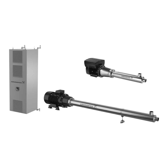
- Page 1 / service-commercial@motralec.com / 01.39.97.65.10 GRUNDFOS INSTRUCTIONS BMS hs, BMS hp, BMST, BMSX Service instructions...
-
Page 2: Table Of Contents
5.5 Dismantling the rotating shaft seal part 5.6 Dismantling the pump and sleeve 5.7 Assembling the pump 5.8 Aligning pump and motor Software 6.1 Grundfos BMS hs 6.2 Grundfos BMS hp Pressure exchanger Fault finding 8.1 BMS hs and BMST 8.2 BMS hp... -
Page 3: Type Key
www.motralec.com / service-commercial@motralec.com / 01.39.97.65.10 2.2 Type key Example BMS 30 -26 hs -E -C -P -A Pump BMSX include X-changer and BM hp pump BMST include BMT pump Rated pump flow rate [m Number of stages Type High-pressure pump with high-speed High inlet pressure Motor Materials... -
Page 4: Service Tools 4 Note
The PM Leroy-Somer motor and drive are available at the Leroy- Somer website, see http://www.emersonindustrial.com/ For further information, see the online documents below: • Grundfos quick guide for BMS hs, BMS hp, BMST and BMSX: http://net.grundfos.com/qr/i/98737800 • Grundfos installation and operating instructions for BMS hs BMShp, BMST and BMSX: http://net.grundfos.com/qr/i/... -
Page 5: Before Dismantling
www.motralec.com / service-commercial@motralec.com / 01.39.97.65.10 4. Loosen the clamps and pull the pump towards the outlet port if 5. Before dismantling the pump is mounted on a base frame. General information about BMS hs and BMS hp The work site must be clean, free of salt or brine water and iron filings. -
Page 6: Dismantling The Thrust Bearing And Shaft Seal
www.motralec.com / service-commercial@motralec.com / 01.39.97.65.10 7. Pull back the thrust bearing and shaft from the bearing 2. Remove the four pins. housing. Shaft bearing with shaft Fig. 7 Fig. 10 Removing the pins 8. Remove the two O-rings. 3. Pull out the thrust bearing and support. Note: Always replace the O-rings and use soapy water for Note: Inspect the up-thrust bearing surfaces, stationary and lubrication. -
Page 7: Assembling The Thrust Bearing
www.motralec.com / service-commercial@motralec.com / 01.39.97.65.10 8. Note down the position of the holes in the thrust bearing. 5.4 Assembling the thrust bearing 5. Note down the position of the pin. Fig. 13 Position of the pin 6. Note down the position of the hole. Fig. -
Page 8: Dismantling The Rotating Shaft Seal Part
www.motralec.com / service-commercial@motralec.com / 01.39.97.65.10 5. Remove the support bearing and replace it. 5.5 Dismantling the rotating shaft seal part 1. Loosen and remove the shaft seal (left-hand thread). For service tool, see section 4. Service tools. Fig. 18 Loosening the shaft seal Fig. -
Page 9: Dismantling The Pump And Sleeve
Fig. 27 Separating the pump and sleeve Fig. 24 Assembling the thrust bearing 12. Pull out the pump. 13. Check the SP service instruction in Grundfos Product Center 5.6 Dismantling the pump and sleeve for more information about dismantling and repairing the 9. -
Page 10: Assembling The Pump
www.motralec.com / service-commercial@motralec.com / 01.39.97.65.10 15. Replace the O-ring. 18. Loosen the union nut by 90 ° angle. Use markings if needed. The union nut is loosen again in order to create a small gap between the pump and sleeve flange. Fig. -
Page 11: Aligning Pump And Motor
www.motralec.com / service-commercial@motralec.com / 01.39.97.65.10 5.8 Aligning pump and motor Step Description Picture 5.8.1 Before aligning pump and motor Before aligning the pump and motor, make sure that the drain holes are pointing downwards. At the same time, the inlet pipe When you have must point upwards (position 12 o'clock). - Page 12 www.motralec.com / service-commercial@motralec.com / 01.39.97.65.10 5.8.3 Positioning the inlet pipe To change the position of the pipe, follow this procedure. Step Description Picture Remove the M10 bolts. Loosen the M12 bolts. Mark up the pump sleeve and union nut. Turn the inlet pipe to the needed position, and make sure the union nut follows.
-
Page 13: Software
5. Save the changes and exit the program. 6. Remove the USB connection. 6.2 Grundfos BMS hp Grundfos BMS hp is setup by factory. The settings are default settings for a Grundfos BMSX application. You can change the user specific parameters (duty point etc.) via either: •... -
Page 14: Pressure Exchanger
See the pressure exchanger nameplate. Warning If you detect an abnormal sound, do not dismantle the unit. This action can void the warranty. Instead, call Grundfos Service. You find information about the pressure exchanger on this website: http://www.energyrecovery.com. 8. Fault finding 8.1 BMS hs and BMST... -
Page 15: Bms Hp
www.motralec.com / service-commercial@motralec.com / 01.39.97.65.10 8.2 BMS hp Warning Before starting work on the product, make sure that the power supply has been switched off and that it cannot be accidentally switched on. Fault Possible cause Remedy 1. The pump stops a) No or insufficient water supply. -
Page 16: Pressure Exchanger
(publication number 98567337). b) Debris or foreign particles in the device. Contact Grundfos Service. c) The system is not properly flow-balanced. See section in the BMS hp, BMS hs installation... -
Page 17: Checking The Motor And Cable
www.motralec.com / service-commercial@motralec.com / 01.39.97.65.10 9. Checking the motor and cable 1. Supply voltage When the motor is loaded, the voltage must be within ± 5 % of the rated voltage. If the voltage varies more than that, the motor may burn. Measure the voltage between the phases with If the voltage is constantly too high or too low, replace a voltmeter. -
Page 18: Drawings
www.motralec.com / service-commercial@motralec.com / 01.39.97.65.10 10. Drawings 345a... - Page 19 www.motralec.com / service-commercial@motralec.com / 01.39.97.65.10...
-
Page 20: Data Report, Powerdrive
/ service-commercial@motralec.com / 01.39.97.65.10 11. Data report, POWERDRIVE To be completed by the Grundfos Service Technician servicing the equipment – complete all questions. Date of intervention Pump Start Date Drive Serial No. Failure Date Motor Serial No. Total Hours Part No.
Need help?
Do you have a question about the BMS Series and is the answer not in the manual?
Questions and answers