Grundfos CU 301 Installation And Operating Instructions Manual
Hide thumbs
Also See for CU 301:
- Installer manual (28 pages) ,
- Installation and operating instructions manual (89 pages)
Table of Contents
Advertisement
Advertisement
Table of Contents

Related Manuals for Grundfos CU 301


Summary of Contents for Grundfos CU 301
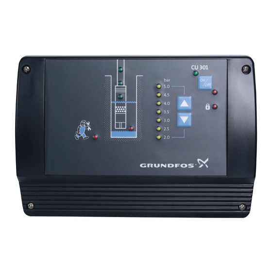
- Page 1 GRUNDFOS INSTRUCTIONS CU 301 Installation and operating instructions...
-
Page 2: Limited Warranty
Products which are sold but not manufactured by Grundfos are subject to the warranty provided by the manu- facturer of said products and not by Grundfos' warranty. Grundfos will not be liable for damage or wear to products caused by abnormal operating conditions, accident, abuse, misuse, unauthorized alteration or repair, or if the product was not installed in accordance with Grundfos' printed installation and operating instructions. - Page 3 CU 301 Installation and operating instructions...
-
Page 4: Table Of Contents
5.3.1 Sensor 5.3.2 Choice of sensor 5.3.3 Maximum pressure setting 5.3.4 Automatic restart 5.3.5 Dry-running stop 5.3.6 Maximum speed 5.3.7 Cut-in speed 5.3.8 Buttons on the CU 301 5.3.9 Indication of pump operation 5.3.10 Number Print Troubleshooting Service Technical data Electrical connection 8.1.1 Mains supply... -
Page 5: Constant-Pressure Control
1. Constant-pressure control CU 301 The control unit CU 301 is for use only with Grundfos CU 301 SQE pumps incorporating electronic power factor correction (PFC). 1.1 Description The system maintains a constant pressure within the maximum pump performance in spite of a varying water consumption. - Page 6 Flow detection The pump starts as a consequence of During pump operation, i.e. when water is con- sumed, the CU 301 will adjust the pump speed to • a high flow or maintain a constant pressure. In order to stop the •...
-
Page 7: System Sizing
22 SQE-80 system pressure. 22 SQE-120 Comment: If this is not fulfilled, the pressure may fall below the pressure set on the CU 301. 22 SQE-160 Maximum head at rated flow and minimum head at 22 SQE-190 no flow can be found in the following sections. -
Page 8: Positioning The Pressure Sensor
1.6 Precharge pressure setting The CU 301 is designed to work with a 2 gal. dia- phragm tank. The precharge pressure of the diaphragm tank must be set to 70% of the pressure setting in order to use the tank to the limit of its capacity. -
Page 9: Operating Functions
2.3 Pressure setting flashing ing with the R100. The two arrow buttons on the CU 301 front are used for the pressure setting, see fig. 10. * If the On/Off button has been used to stop the pump, this button must also be used for restarting. -
Page 10: Button Locking
The alarm functions indicated on the Setting range: 40-100 psi. CU 301 front are described in the following sections. Arrow-up button 3.1 Service alarm When this button is pressed, the system pressure If one or more factory-set alarm values are setting is increased in steps of 10 psi. -
Page 11: Dry-Running Protection
5 seconds, and the motor speed is within 1,000 rpm of the maximum speed setting as defined in the section 5.3.6, the CU 301 stops the pump and declares a dry-running alarm. When the motor is stopped, the dry-running indicator light is permanently on, see fig. -
Page 12: Position Of Leds
Permanent red light when the supply voltage is out of range, see section Voltage alarm *) 8. Technical data. Permanent red light when communication between the CU 301 and the No contact to pump *) pump is impossible. *) Press the On/Off button to reset the alarm indication. -
Page 13: Cu 301 With R100
The R100 communicates via infrared light. During communication, there must be visual contact between the CU 301 and the R100. The best visual contact between the two units is obtained by pointing the R100 at the lower arrow button or by removing the front cover and pointing the R100 at the right side of the CU 301, see fig. -
Page 14: Menu Overview
0. GENERAL 1. OPERATION 2. STATUS 3. INSTALLATION 5.3.1 5.2.1 5.1.1 5.1.2 5.2.2 5.3.2 5.2.3 5.1.3 5.3.3 5.1.3 5.2.4 5.3.4 5.3.5 5.2.5 5.2.6 5.3.6 5.3.7 5.3.8 5.3.9 5.3.10 Fig. 16 Menu overview... -
Page 15: Menu Operation
5.1 Menu OPERATION 5.1.3 Alarm The OPERATION menu for the CU 301 offers the possibility of setting and reading operating parame- ters. Factory settings are marked in bold-faced type under each individual display. 5.1.1 Pressure setting This display shows the current alarm status. -
Page 16: Menu Status
5.2 Menu STATUS 5.2.3 Speed The STATUS menu for the CU 301 provides operat- ing data about pump/motor and sensor. It is not pos- sible to change or set values in this menu. When [OK] is pressed continuously in this display, the displayed value is being updated. -
Page 17: Operating Hours And Number Of Starts
• Sensor output signal: "–" (not active), 0-20 mA, The setting of this display overrules the possibility of using the arrow button on the CU 301 front to 4-20 mA, 0-10 V, 2-10 V. increase the pressure to a setting above the •... -
Page 18: Automatic Restart
5.3.4 Automatic restart Relation to other displays The actual pump power input can be read in display 5.2.5 Power input and power consumption. If the maximum pump speed has been reduced in display 5.3.6 Maximum speed, the dry-running stop value must be changed. 5.3.6 Maximum speed Set the automatic restart time from stop, caused by an alarm, to restart attempt. -
Page 19: Buttons On The Cu 301
• Running light • Constant light. 5.3.10 Number Allocate a number to the CU 301 and the pump con- nected. The CU 301 and the pump must have the same number. The CU 301 control unit communicates with the SQE... -
Page 20: Print
6. Print The actual data in the R100 can be printed on a Hewlett-Packard printer type HP82240B. Navigate the R100 to the print menu and point the R100 at the IR sensor of the printer and press [OK]. The following information will be printed:... -
Page 21: Troubleshooting
• No contact to pump. To identify the cause of the service alarm, it is necessary to remove the front cover from the CU 301 or use the R100. Fit the front cover as shown in fig. 18 to avoid disconnecting the multi-core cable. - Page 22 If the pump has not started yet, proceed as follows: • Press the On/Off button for 5 seconds. If the pump starts, the CU 301 or the sensor may be defective. Note: The pressure is not controlled and may rise to a high level.
- Page 23 If the pump has already worked satisfactorily with a cates "No contact to MSE 3. CU 301 or a CU 300, the motor can be expected to be pump". an MSE 3. There is no technical way of determining the motor type.
- Page 24 7. The CU 301 indi- a) The supply voltage is Check - possibly over a period of time - that the supply cates "Overvoltage" unstable or outside voltage is according to the values below. or "Undervoltage". the voltage range • Motor type 0.5 hp = 198-315 V specified for the in- •...
-
Page 25: Technical Data
100 mA. Disconnect the sensor in order to determine if it is de- fective. Replace defective sensor. No: The load is OK, but the CU 301 sensor input may be defective. 14. The pump is operat- a) No communication. Check that the LED "No contact to pump" is on. -
Page 26: Electrical Connection
SQE-NE SQE-NE SQE-NE All models 0.5 hp 0.75 hp 1.0 hp 1.5 hp Sensor defective 4-20 mA (the value is stored in the CU 301) Overload 5.2 A 8.4 A 11.2 A 12 A 11 A Stop limit: Stop limit:... -
Page 27: Mains Supply
POWER PUMP Fig. 20 Electrical connection of the CU 301 In situations where multiple CU 301 pump power Legend cables are run parallel in wiring trays or conduit and less than 10-12 inches apart, the possibility for Pos. Description undesired communication between units exists. -
Page 28: Pressure Sensor Voltage Chart
9. Pressure sensor voltage chart Voltage to pressure chart for CU 301 pressure sensors. Measure the DC voltage between "SENSOR IN" and "SENSOR GND". Voltages lower than 2 or higher than 10 indicate an incorrectly wired or a faulty sensor. -
Page 29: Disposal
This product or parts of it must be disposed of in an environmentally sound way: 1. Use the public or private waste collection service. 2. If this is not possible, contact the nearest Grundfos company or service workshop. Subject to alterations. - Page 30 U.S.A. Canada Mexico GRUNDFOS Pumps Corporation GRUNDFOS Canada Inc. Bombas GRUNDFOS de Mexico 17100 West 118th Terrace 2941 Brighton Road S.A. de C.V. Olathe, Kansas 66061 Oakville, Ontario Boulevard TLC No. 15 Phone: +1-913-227-3400 L6H 6C9 Parque Industrial Stiva Telefax: +1-913-227-3500...
- Page 31 Being responsible is our foundation Thinking ahead makes it possible Innovation is the essence 5/06 L-SP-TL-019 www.grundfos.com...
Need help?
Do you have a question about the CU 301 and is the answer not in the manual?
Questions and answers