Table of Contents
Advertisement
Quick Links
Download this manual
See also:
Quick Manual
Advertisement
Table of Contents

Related Manuals for Grundfos MFV


Summary of Contents for Grundfos MFV
- Page 1 GRUNDFOS INSTRUCTIONS Multi-function valve MFV Installation and operating instructions...
-
Page 2: Table Of Contents
If you require further information or if any problems arise, 1.3 Safe operation which are not described in detail in this manual, please contact 1.4 Safety instructions for the operator/user Grundfos. General information 2.1 Applications 1.1 Symbols used in this document 2.2 Improper operating methods... -
Page 3: General Information
PVC, PP 0 °C to +40 °C 0 °C to +20 °C considered improper and are not permitted! Grundfos PVDF -10 °C to +40 °C -10 °C to +20 °C cannot be held liable for any damage resulting from incorrect use! 2.2 Improper operating methods... -
Page 4: Type Key
3.3 Type key Code Example 5/8- Multi-function valve Pump connection G 5/8 Relief pressure 10 + 2 bar 16 + 2 bar Connection material Polypropylene Polyvinyl chloride Polyvinylidene fluoride (PVDF) Gasket material EPDM PTFE Connection, discharge side/relief side Combined connection for hose 4/6 mm, 6/9 mm, 9/12 mm Combined connection for hose 0.17"... -
Page 5: Dimensional Drawings
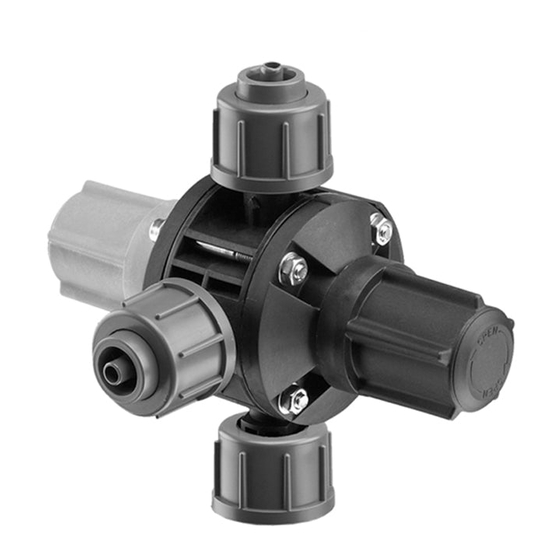
3.5 Dimensional drawings Pos. Description Valve inlet Valve outlet Relief outlet G 5/8 Connections Fig. 2 1. Screw the inlet (A) onto the pump discharge valve. 2. Connect the discharge line to the outlet (B). G 5/8 3. Connect the relief line to the relief outlet (C), and direct the unpressurised liquid to the tank or a suitable overflow. -
Page 6: Setting The Opening Pressure
5.3 Deaerating the pump 16 + 2 bar Before starting up the pump, it can be depressurised and 10 + 2 bar deaerated using the multi-function valve (see fig. 5). 7 + 2 bar • To deaerate the pump, turn the green deaeration knob (1) clockwise (direction of arrow on protective cap) as far as it will •... -
Page 7: Maintenance
8. Disposal This product or parts of it must be disposed of in an environmentally sound way. Use appropriate waste collection services. If this is not possible, contact the nearest Grundfos company or service workshop. Subject to alterations. - Page 9 Telefax: +852-27858664 Telefax: +47-22 32 21 50 Canada Turkey GRUNDFOS Canada Inc. Hungary Poland GRUNDFOS POMPA San. ve Tic. Ltd. Sti. 2941 Brighton Road GRUNDFOS Hungária Kft. GRUNDFOS Pompy Sp. z o.o. Gebze Organize Sanayi Bölgesi Oakville, Ontario Park u. 8 ul.
- Page 10 96772109 1116 ECM: 1196441 www.grundfos.com...
Need help?
Do you have a question about the MFV and is the answer not in the manual?
Questions and answers