Table of Contents
Advertisement
CONTENTS
1.
2.
2.1
2.2
2.3
3.
3.1
4.
4.1
4.2
4.3
4.4
5.
6.
6.1
6.2
6.3
7.
8.
9.
9.1
9.2
9.3
9.4
9.5
9.6
9.7
9.8
9.9
10.
11.
12.
13.
14.
15.
Warning
Prior to installation, read these
installation and operating instructions.
Installation and operation must comply
with local regulations and accepted
codes of good practice.
6
1. Symbols used in this document
Page
Warning
6
If these safety instructions are not
7
observed, it may result in personal
7
injury!
7
8
If these safety instructions are not
8
observed, it may result in malfunction
Caution
8
or damage to the equipment!
8
9
Notes or instructions that make the job
9
easier and ensure safe operation.
9
9
9
10
11
11
11
13
13
13
13
13
13
13
13
13
13
14
14
15
16
16
16
16
16
16
Advertisement
Table of Contents

Related Manuals for Grundfos CU 361


Summary of Contents for Grundfos CU 361
-
Page 1: Table Of Contents
Digital outputs (relay outputs) Conductors Battery backup (UPS) Terminal groups Overview of inputs and outputs Maintenance Service Replacing the CU 361 13.1 Replacing the CIM module Dimensions Disposal Warning Prior to installation, read these installation and operating instructions. Installation and operation must comply with local regulations and accepted codes of good practice. -
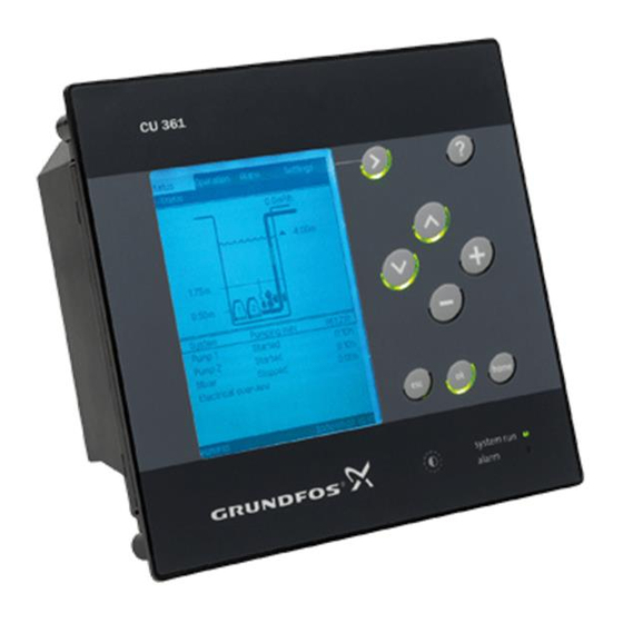
Page 2: Product Description
2. Product description 2.1 Indicator lights The CU 361 has one green and one red indicator The CU 361 is a control unit designed for Dedicated light. Controls systems. The CU 361 is used for the control and monitoring of one or two pumps in a wastewater The green indicator light is on when the power pit. -
Page 3: Potentially Explosive Environments
Controller series 3. Identification Model number The CU 361 can be identified by means of the nameplate on the back. See fig. 3. 4. Installation The CU 361 is only intended for factory wiring. Before installation, check that the CU 361... -
Page 4: Location
Dimensions of the CU 361, see section minimum IPX4. 14. Dimensions. 4.2 Enclosure class The CU 361 is IP54 when mounted in the front of an IPX4 enclosure. The cabinet must be of a flame- retardant material. For USA and Canada... -
Page 5: Emc-Correct Installation
Signal conductors for digital and analog inputs and outputs should be screened, i.e. run the screen all the way to the CU 361 and connect it to frame with for instance a cable clamp. Alternatively, the signal conductors in the panel may be unscreened if the panel is divided into a power and a low-voltage area. -
Page 6: Internal Genibus Connection To The Io 351 And Io 111
6.1 Internal GENIbus connection to the IO 351 and IO 111 The CU 361, IO 351 and IO 111 communicate via GENIbus. CU 361 IO 111 IO 351 Fig. 9 GENIbus connection to the IO 351 and IO 111* (* optional) 6.2 Fieldbus communication interface... - Page 7 Fig. 13 Placing the new labels on the back cover 3. Fit the CIM module. See fig. 12. 5. Refit the back cover to the CU 361, and secure it with the mounting screw. See fig. 14. Fig. 12 Fitting the CIM module...
-
Page 8: Start-Up
7. Start-up 9.4 Digital inputs Start-up must be carried out by authorised Open-circuit voltage 24 VDC personnel. Closed-circuit current 5 mA, DC Warning Frequency range 0-4 Hz Prior to start-up, read the installation and operating instructions for the 9.5 Analog inputs product in question. -
Page 9: Battery Backup (Ups)
9.8 Battery backup (UPS) 9.9 Terminal groups A battery can be connected to the CU 361 as backup for the normal power supply. The battery can be connected directly to the CU 361 without a fuse. With the backup battery the CU 361 can continue to operate despite interruptions in the normal power supply. -
Page 10: Overview Of Inputs And Outputs
NO: Normally open contact Common. Position numbers, see fig. 2. Pos. Terminal Designation Data Diagram Connection to phase CU 361 conductor 1 x 100-240 VAC ± 10 %, 50/60 Hz Connection to neutral conductor Connection to protective earth RS-485 A CU 361... -
Page 11: Maintenance
12. Service The CU 361 cannot be serviced. If the CU 361 is faulty, the unit must be replaced. See section 13. Replacing the CU 361. 13. Replacing the CU 361 1. Switch off the power supply to the CU 361.
Need help?
Do you have a question about the CU 361 and is the answer not in the manual?
Questions and answers