
Subscribe to Our Youtube Channel
Related Manuals for Grundfos BMST Series


Summary of Contents for Grundfos BMST Series
- Page 1 GRUNDFOS INSTRUCTIONS BMS hs, BMST, BMSX Installation and operating instructions...
- Page 2 Declaration of conformity GB: EC declaration of conformity DK: EF-overensstemmelseserklæring We, Grundfos, declare under our sole responsibility that the product Vi, Grundfos, erklærer under ansvar at produktet BMS som denne BMS, to which this declaration relates, is in conformity with these Council erklæring omhandler, er i overensstemmelse med disse af Rådets...
-
Page 3: Table Of Contents
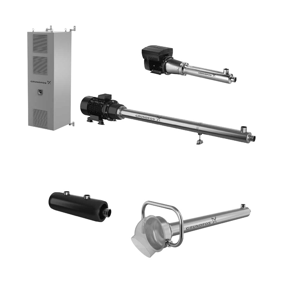
BMS hs pump 2. Product introduction BMST system BMSX system Grundfos BMS, BMST and BMSX booster systems are designed for desalination of seawater or brackish water in reverse osmosis Electrical installation systems, the so-called SWRO systems (SWRO = Sea Water BMS hs pump Reverse Osmosis). -
Page 4: Nameplate
TR mark and stops. 2.3 Commissioning Fresh water Commissioning of BMSX booster systems must be carried out by Max. salinity Flush time Pump type certified Grundfos employees to ensure long and trouble-free [ppm TDS] [min.] [bar] operation. BMS hs 1000 5-10... -
Page 5: Before Installation
3. Before installation 1. Check that the pump has not been damaged during transportation. 2. Check that the type designation corresponds to the order. See the pump nameplate. 3. Compare the motor voltage and frequency details on the motor and frequency converter nameplates with the power supply available. -
Page 6: Foundation
4.1.3 Motor installation 4.1.5 Alignment of motor and pump Align the motor and pump before you tighten the bolts. To ensure Caution Use vibration dampers. correct installation, follow this procedure: The motor must be level. If there is a gap between the foundation and motor, use a spirit level, a feeler gauge and shims to level the Step Description Picture... - Page 7 4.1.6 Position of the inlet pipe 4.1.7 Flushing the system If you want to change the position of the pipe, follow this To avoid impurities in the pump, flush the pipes procedure. Caution before you connect the pump inlet and discharge pipes.
-
Page 8: Bmst System
Discharge pipe 4.2 BMST system In order to facilitate service of the pump and motor, it is important A BMST system is built by using a BMS hs as primary pump and that the delivered service connector is built into the system. a BMT as secondary pump. - Page 9 4.2.5 Inlet and discharge pipes (BMT and BMS hs pump) The inlet and discharge pipes are fitted with clamp liners for Victaulic couplings. Min. 30° To ensure correct installation, follow this procedure. Step Description Picture The turbine is driven by the high-pressure concentrate from the membrane.
-
Page 10: Bmsx System
4.3.1 Installation of BMS hs pump See section 4.1 BMS hs pump. 4.3.2 Installation of BM hp pump See the installation and operating instructions for Grundfos BM and BM hp. 4.3.3 Pressure exchanger Fig. 18 Pressure exchanger... -
Page 11: Electrical Installation
If installing a BMS hs pump, you are now ready for commissioning. See section 6.1 BMS hs system. 5.2 BMS hp pump See the installation and operating instructions for Grundfos BM and BM hp. See the nameplate to identify the motor type and type of control board. -
Page 12: Bmst System
6.1.2 Startup 6.2 BMST system If a discharge valve is installed, we recommend that you open the 6.2.1 Before startup valve 1/4 of a turn when starting the pump/system. Follow these instructions to ensure correct startup of the BMST system. Note Never operate pumps against a closed valve. -
Page 13: Bmsx System
6.2.2 Startup 6.3.2 Before startup To start up a BMST system, proceed as follows: Follow these instructions to ensure correct startup of the BMSX system. 1. Start the raw-water feed pump (1), and check that the inlet pressure (2) of the pump is higher than 2.0 bar (20 metres Check the following: head) and lower than 5.0 bar (50 metres head). - Page 14 6.3.3 Startup To start up a BMSX system, proceed as follows: 1. All valves should be in their normal operating positions. 2. Start the raw-water feed pump (1). When the raw-water feed pump is started, the system is filled with water. Ensure that the entire system is vented.
-
Page 15: Low-Pressure Flow Control
A lower flow in the seawater inlet than the seawater discharge will 7. Shutdown result in lower-quality permeate, increased feed pressure and Carefully follow these instructions to safely shut down your higher energy consumption. We recommend that you use a booster system. -
Page 16: Bmst System
7.2 BMST system 7.3 BMSX system This procedure describes how to shut down the BMST system. This procedure describes how to shut down the BMSX system. 1000 ppm TDS Fig. 30 Example of BMST system Procedure 1. Ramp down the BMS hs pump (6.1) according to factory Fig. -
Page 17: Flushing
7.4 Flushing 9. Periods of inactivity BMS pumps can be flushed in the flow direction. Prior to periods of inactivity, various precautions must be taken to protect the system. Flushing of the booster pumps is very important, especially when the pumps are used for pumping salt water or water with The specific precautions to be taken if the system is to be inactive chemicals. -
Page 18: Fault Finding
10. Fault finding 10.1 BMS hs and BMST Warning Before starting work on the product, switch off the power supply. Make sure that the power supply cannot be accidentally switched on. Fault Possible cause Remedy 1. The pump stops/starts a) No water supply. Check that the low-pressure switch functions normally occasionally during The low-pressure switch has cut out. -
Page 19: Bm Hp
10.2 BM hp Warning Before starting work on the product, switch off the power supply. Make sure that the power supply cannot be accidentally switched on. Fault Possible cause Remedy 1. The pump stops a) No or insufficient water supply. The pressure Check that the pressure switch functions normally occasionally during switch has cut out. -
Page 20: Pressure Exchanger
See section 6.3 BMSX system. audible rotation). pressure or below the rated flow capacity. b) Debris or foreign particles in the device. Contact Grundfos Service Department. c) The system is not properly flow-balanced. See section 6.3 BMSX system. 6. Low concentrate flow. -
Page 21: Checking The Motor And Cable
11. Checking the motor and cable 1. Supply voltage When the motor is loaded, the voltage should be within ± 5 % of the rated voltage. If the voltage varies more than that, the motor may burn. Measure the voltage between the phases with If the voltage is constantly too high or too low, the a voltmeter. -
Page 22: Technical Data
This product or parts of it must be disposed of in an environmentally sound way: 1. Use the public or private waste collection service. 2. If this is not possible, contact the nearest Grundfos company or service workshop. Subject to alterations. - Page 23 Turkey 20th km. Athinon-Markopoulou Av. Тел.: +7 (375 17) 286 39 72, 286 39 73 New Zealand GRUNDFOS POMPA San. ve Tic. Ltd. Sti. P.O. Box 71 Факс: +7 (375 17) 286 39 71 GRUNDFOS Pumps NZ Ltd. Gebze Organize Sanayi Bölgesi GR-19002 Peania E-mail: minsk@grundfos.com...
- Page 24 98567337 1013 ECM: 1122748 www.grundfos.com...
Need help?
Do you have a question about the BMST Series and is the answer not in the manual?
Questions and answers