Table of Contents
Advertisement
A - C L A S S
BoilerMate OV
DESIGN, INSTALLATION AND
SERVICING INSTRUCTIONS
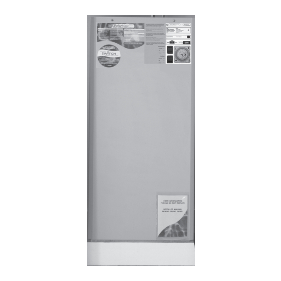
PLEASE LEAVE THESE INSTRUCTIONS IN THE POCKET PROVIDED ON
THE BACK OF THE FRONT PANEL
Gas Council Approved Reference Numbers
BMA 125 OV
BMA 145 OV
BMA 185 OV
BMA 210 OV
BMA 225 OV
benchmark
TM
AN OPEN VENTED CENTRAL HEATING
The code of practice for the installation,
AND MAINS PRESSURE HOT WATER SUPPLY
commissioning & servicing of central heating systems
SYSTEM INCORPORATING
A THERMAL STORE
ALL MODELS COMPLY WITH THE
WATER HEATER MANUFACTURERS
SPECIFICATION FOR INTEGRATED THERMAL
STORES
Advertisement
Table of Contents

Subscribe to Our Youtube Channel
Related Manuals for gledhill benchmark BoilerMate A-Class OV Series


Summary of Contents for gledhill benchmark BoilerMate A-Class OV Series
- Page 1 A - C L A S S BoilerMate OV DESIGN, INSTALLATION AND SERVICING INSTRUCTIONS PLEASE LEAVE THESE INSTRUCTIONS IN THE POCKET PROVIDED ON THE BACK OF THE FRONT PANEL Gas Council Approved Reference Numbers BMA 125 OV BMA 145 OV BMA 185 OV BMA 210 OV BMA 225 OV...
-
Page 2: Table Of Contents
Quality System audited by BSI. Patents Pending As part of the industry wide “Benchmark” Initiative all Gledhill BoilerMates now include a Benchmark Installation, Commissioning and Service Record Log Book. Please read carefully and complete all sections relevant to the appliance installation. -
Page 3: Introduction
Sale, which are set out at the rear of this manual. In the interest of continuously improving the BoilerMate range, Gledhill Water Storage Ltd reserve the right to modify the product without notice, and in these circumstances this document, which is accurate at the time of printing, should be disregarded. - Page 4 ���� ���� ��������� ������ ����� ��� �������� ������ ��� ������� ������ ������������ Gledhill are part of the‘Benchmark’scheme and ���������� ������������ ������� ������ ���� a separate commissioning/service log book is ������� �� ��� ��������� �� � ���� ���� �������...
-
Page 5: Technical Data
1.0 DESIGN 1.2 TECHNICAL DATA Model BMA 125 OV BMA 145 OV BMA 185 OV BMA 210 OV BMA 225 OV Weight (empty) Weight (full) DHW Pump Grundfos UPR 15/50 Grundfos UPR 15/50 Grundfos UPR 15/50 Grundfos UPR 15/50 Grundfos UPR 15/50 Heating Pump Grundfos UPS 15/50 Grundfos UPS 15/50... - Page 6 1.0 DESIGN 1.2 TECHNICAL DATA Standard Equipment The standard configuration of the BoilerMate A-Class OV is shown opposite. The Appliance Control Board (A.C.B.), mounted inside the appliance, controls the operation of the complete system. The A.C.B. is pre-wired to a terminal strip where all electrical connections terminate.
- Page 7 1.0 DESIGN 1.2 TECHNICAL DATA ��� ����������� ������ �� ������ ���� ��� ����� ����������� APPLIANCE DIMENSIONS � � � ������� MODEL Height Width Depth BMA 125 OV 960mm 530mm 595mm BMA 145 OV 1000mm 530mm 595mm � BMA 185 OV 1040mm 530mm 595mm...
- Page 8 1.0 DESIGN 1.2 TECHNICAL DATA ��� �� ��� �� ��� � � �� ��� ��� ���� �� �� ���� ��� ��� ��� ��� ��� ���������� �� �� � �� ������ ���� �� �������� ��� ���������� ������� ����� ��� �������� �� �� ������������ ���� �� ����� ��� ���� ���� �� �������...
-
Page 9: Issue 3
1.0 DESIGN 1.2 TECHNICAL DATA ����������� ����������� Appliance Control Board The appliance control board (shown opposite) �� ��� has a 2 digit display and 2 push buttons which ��������� ����������� ����������� are used to check the status of the appliance, ��������... - Page 10 1.0 DESIGN 1.2 TECHNICAL DATA Sensor Tempature Readings Details of the various sensors S1-S6 used in the BoilerMate A-Class are shown opposite. The sensor reference i.e. S1 and the actual temperature at that sensor flash alternately on the display when selected. Sensors used in BoilerMate A-Class Sensor Sensor...
-
Page 11: System Details
fitted in Gledhill. the system a pressure limiting (reducing) valve set to 3 bar will be required. The hot water flow rate from the BoilerMate If you encounter a situation where the water pressure is adequate but flow rates are... - Page 12 flow/ important in any mains pressure system, that the piping in a dwelling should be pressure outlets please discuss with the Gledhill sized in accordance with BS 6700. This is particularly important in a large property technical department.
- Page 13 1.0 DESIGN 1.3 SYSTEM DETAILS Heating System ����� ���� ���������������� General ���� ����� A schematic layout of the heating system in a typical small dwelling is shown opposite. ������ ��� ���� The flow and return from the boiler must always run directly to the BoilerMate A-Class ����...
- Page 14 1.0 DESIGN 1.3 SYSTEM DETAILS Heating System It is also essential that if an alternative pipework Pipe Sizing/Materials material/system is chosen the manufacturer confirms that the design criteria of the new The primary pipework connecting the boiler and the thermal store should be sized system is at least equivalent to the use of BS/EN to achieve a maximum of 8°C rise across the boiler or the maximum temperature Standard copper pipework and fittings.
- Page 15 1.0 DESIGN 1.3 SYSTEM DETAILS Heating System Boiler sited above the BoilerMate Any boiler used must be fitted with an overheat ���� ��������� ��� ���� thermostat i.e. it must be suitable for use in ���� ������� ����� ����� a sealed system. �...
- Page 16 1.0 DESIGN 1.3 SYSTEM DETAILS Heating System Connection of Bathroom Radiator/ Towel-Rail for Summer use � � � ������� �������� If a pumped circuit is required for the bathroom radiator/towel rail, the flow pipework can be teed anywhere into the primary flow between the boiler and the BoilerMate.
- Page 17 The BoilerMate A-Class appliances will not be suitable if the primary pipework dips or the boiler is located above the BoilerMate. For further details please ring the Gledhill Technical helpline. Page 17...
- Page 18 1.0 DESIGN 1.3 SYSTEM DETAILS ������� ���������� ‘Switch’ ��� ������ The BoilerMate A-Class is supplied with ‘Switch’ ���� �������� �������� ������� which provides a 6kW electrical emergency ������ �������� �������� ������ �������� ����� �������� �������� ������ ���� back up in the case of failure of the main heat ��...
-
Page 19: Installation
2.0 INSTALLATION 2.1 SITE REQUIREMENTS An electrical supply must be available which is The appliance is designed to be installed in an airing/cylinder cupboard and the correctly earthed, polarized and in accordance relevant minimum dimensions are provided in section 1.2 Technical Data. with the latest edition of the IEE requirementsfor electrical Installations BS 7671. -
Page 20: Installation
2.0INSTALLATION 2.2 INSTALLATION Preparation/placing the appliance in position. Details of the recommended positions for termination of the first fix pipework are provided in section 1.2 Technical Data. The pipework can be located or its position checked using the template provided with each appliance. - Page 21 2.0INSTALLATION 2.2 INSTALLATION Pipework connections The position of the pipework connections is shown opposite. The connection sizes and dimensions are listed in Section 1.2 Technical Data. All the connections are also labelled on the appliance. It is essential that the pipework is connected to the correct connection.
- Page 22 DATE : AUGUST 2005 ISSUE No : 4 IS RESERVED. IT IS NOT TO BE REPRODUCED COPIED OR DISCLOSED TO A THIRD PARTY EITHER WHOLLY OR IN PART WITHOUT OUR APPROVED WRITTEN CONSENT. © GLEDHILL WATER STORAGE LTD. Page 22...
- Page 23 Boiler Pump Pump * All wire sizes 0.5mm² unless otherwise stated TITLE JOB NAME GLEDHILL WATER STORAGE LTD. Electrical Schematic for BOILERMATE 'A' class BOILERMATE 'A' Class SYCAMORE TRADING ESTATE appliance with factory fitted clock with Clock (Factory Standard) SQUIRES GATE LANE BLACKPOOL DRG.
- Page 24 2.0 INSTALLATION 2.2 INSTALLATION It is normally envisaged that the feed and expansion cistern will be located in the same cupboard as the BoilerMate appliance itself to maintain a dry roof space. The cold feed/open vent pipework assembly (as supplied) should be used if it is intended to install the F &...
- Page 25 2.0 INSTALLATION 2.2 INSTALLATION Electrical Connection - Standard Appliance The BoilerMate A-Class OV is pre-wired to DIN rail terminals from the A.C.B. and plumbers are well able to complete the electrical installation provided they adhere strictly to the IEE Requirements for Electrical Installations BS 7671.
- Page 26 2.0 INSTALLATION 2.2 INSTALLATION The BoilerMate A-Class incorporates a pump overrun for the boiler pump and terminal L1 on the terminal strip (as shown on page 23) should only be used if the boiler requires a permanent live for another purpose. The boiler manufacturers wiring instructions should be read in conjunction with this manual.
- Page 27 2.0 INSTALLATION 2.2 INSTALLATION WARNING Electrical Power Supplies - BoilerMate : THE BOILERMATE A-CLASS IS FITTED WITH AN ELECTRIC BACKUP SYSTEM ‘SWITCH’ . A-Class with Switch. IMPORTANT : ELECTRICIAN/INSTALLER PLEASE NOTE. THE 2 x 16A MCB’s (MCB1 and MCB2) FOR THE ‘SWITCH’ ELECTRIC BACKUP SYSTEM ARE SUPPLIED SET IN ‘OFF’...
- Page 28 2.0 INSTALLATION 2.2 INSTALLATION Zoned heating systems BoilerMate is available in a multi-zone version for use where a property has to have its space heating zoned. Where this appliance version is to be used it is recommended that the BoilerMate ����...
- Page 29 2.0 INSTALLATION 2.2 INSTALLATION Multi-Zone Wiring Diagram Page 29...
-
Page 30: Commissioning
2.0 INSTALLATION 2.3 COMMISSIONING Open the incoming stop valve and fill the domestic mains cold and hot water When using either cleansing or corrosion systems. inhibitor chemical, the manufacturers instructions must be followed. Fill the whole of the primary heating system with potable water through the feed and expansion cistern. - Page 31 2.0 INSTALLATION 2.3 COMMISSIONING Once the system is finally filled turn down the servicing valve for the ballvalve (b) The boiler will not start i.e there will be in the F & E cistern to the point where the warning/overflow will cope with the no 240V ac start signal at BoilerMate terminal discharge arising from a ballvalve failure.
- Page 32 Thisproductiscoveredbythe‘Benchmark’ scheme and a separate commissioning/ should be set at maximum. service log book is included with this product. This must be completed during commissioning and left with the product to meet the Warranty conditions offered by Gledhill. Page 32...
- Page 33 2.0 INSTALLATION 2.3 COMMISSIONING 10. DO ensure that the bypass valve for the heating system (if fitted) is set correctly. 11. DON’T use a combined feed and vent on BoilerMate installations. 12. DON’T use a BoilerMate on a sealed primary i.e.
-
Page 34: Servicing
Gledhill during the in-warranty period (normally 12 months). After this, spares can be obtained direct from Gledhill using the ‘Speed Spares’ service, or through any of the larger plumbers merchants/ specialist heating spares suppliers. Help and advice is also available from the Technical Helpline on 01253 474401. -
Page 35: Short Parts List
3.0 SERVICING 3.3 SHORTS PART LIST Description Supplier/Components Stock Code Models Gas Council PHE pump Grundfos UPR 15-50 (modulating) GT089 Plate heat exchanger (PHE) SWEP 24 Plate heat exchanger GT017 PHE pump isolating valve - inlet Martin Orgee GT133 PHE pump isolating valve - outlet Martin Orgee GT135 CW inlet Y-line strainer... -
Page 36: Fault Finding
3.0 SERVICING 3.4 FAULT FINDING 3. Causes of ‘Unsatisfactory Space Heating’ Despite everyones best efforts some problems could occur and lead to complaints from the householder. Check the boiler thermostat - this should be Complaints can be grouped into the following three main categories:- set at maximum. -
Page 37: Appendix A
APPENDIX A WATER SAVINGS WATER RELATED COSTS CAN BE REDUCED BY GOOD PLUMBING PRACTICE. TAPS & MIXERS 2 TAP 5, 6 OR HALF OPEN OVER 8 L/M 20 L/M Unregulated Fitted with regulator SHOWERS 4 FIXING OPTIONS FOR TAPS & MIXERS 1. -
Page 38: Appendix B
APPENDIX B MANIFOLDS Two sets of manifolds are available as an optional extra. Each set comprises a separate hot and cold water manifold. Both are provided with a 22mm inlet connection t t i t i l located centrally. All outlet connections are 15mm compression. - Page 39 APPENDIX B The pressure loss through a flow regulator at the designated flow rate is about 1.8 bar. Therefore for the flow regulator to control the flow rate at pre-set level,the inlet pressure must be greater than 1.8 bar. If the inlet pressure is lower, the flow rate will be correspondingly less than the pre-set values.
- Page 40 APPENDIX B The size of the distribution pipes supplying the manifold should be calculated using the method set out in BS 6700. A typical diagrammatic arrangement of a system using Manifold Type 1 is shown below. This is only meant to show the principles involved and the actual connection of fittings to the manifold will need to suit the arrangements shown on page 35.
-
Page 41: Appendix C
APPENDIX C G U I D A N C E N O T E S Inhibitor (Corrosion & scale protection of primary heating circuit) On filling the heating system and before the boiler is fired up, it is important to ensure the system water is treated with a suitable corrosion inhibitor, in accordance with the boiler manufacturer’s instructions. -
Page 42: Appendix D
APPENDIX D ������ �������� �� ��������� �������� ����������� �� ������ ��� ���� ��� ���� ������ �� ���� ���� ��� ������ �� �������� ��� ����� �������� ������ ���� ��� ������ �������� ����� ��� ������������ �� ���������� �� � ���� ���������� �������� ������... -
Page 43: Terms & Conditions
�������� ��� ������ �������� ���� �������� ���� ���������� �� ���� � �������� ����� �� �� ���� �� �������� ���� ��� ���������� ����� ������ ����� ��� �� ������ ������ �� �� ����� �� ��� �� ��� ���� �� ������� �� ���� ���� �� �������� ������� ��������... - Page 44 ��� �� ��� ����� ���� ��� ��������� ����� ���� ��� �� ��� ����� ��� ��� ����� ��������� �� ��� ��������� ���� ��� ����� ��� ��������� �� ������� ����� �� � �� ����� �������� �� �������� �� ������ ��� ������� ��� ��������� ����� ��������� ��������...
Need help?
Do you have a question about the benchmark BoilerMate A-Class OV Series and is the answer not in the manual?
Questions and answers