Advertisement
Table of Contents
_____________________________________________________________________________________
DESIGN, INSTALLATION AND SERVICE INSTRUCTIONS
_____________________________________________________________________________________
GENERAL
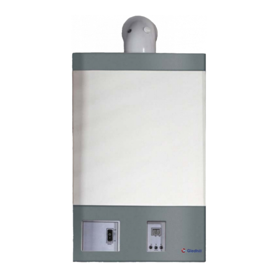
This high efficiency wall mounted condensing boiler is designed to
provide central heating from a fully pumped open vented or sealed
water system when coupled to a thermal store or an indirect cylinder.
The central heating water temperature can be adjusted by the installer
to suit special applications.
Once the controls are set, the boiler operates automatically and the
boiler controller automatically activates the frost protection program to
prevent the boiler from freezing.
This boiler is for use with Natural Gas (G20) only at 20mbar inlet
pressure and is for use in GB &IE only.
Appliance category: I
2H
These instructions cover the following boiler models and only apply to
the appliances sold and installed in Great Britain (GB) and Ireland (IE).
These appliances have been certified for safety and therefore it is
important these instructions must be followed. Both the appliance and
the
installation
specifications
recommended and approved by Gledhill Limited in writing.
alteration not approved by Gledhill Ltd., could invalidate the
certification, boiler warranty and may also infringe the current issue of statutory requirements.
The
Gas
Safety
(Installation
Regulations 1998
"In your own interest, and that of safety, it is law
that all gas appliances are installed by
competent persons, in accordance with the
above regulations. Failure to install appliances
correctly could lead to prosecution."
Control of Substances Harmful to Health
When working with insulation materials, avoid inhalation as it may be harmful to health. Avoid contact with
skin, eyes, nose and throat. Use disposable protection. Dampen the material and ensure that the area is well
ventilated.
INSTRUCTIONS
The instructions are an integral part of the appliance and therefore read these Instructions before installing or
lighting the appliance. Also to comply with the current issue of the Gas Safety (Installation and Use), these
instructions and the 'Benchmark' Log Book must be handed to the user on completion of the installation.
VER: 02.3 _260505
Supplied By www.heating spares.co Tel. 0161 620 6677
A wall mounted high efficiency condensing Gledhill Boiler
Appliance types: C
must
not
be
and
use)
, C
, C
13
73
33
modified
unless
Any
Gledhill wall mounted condensing boiler models
Model
SEDBUK Rating
Reference
GB10
90.1 % - Band 'A'
GB15
90.3 % - Band 'A'
GB20
90.4 % - Band 'A'
GB25
90.4 % - Band 'A'
GB30
90.3 % - Band 'A'
Gas Council
Number
Page:1/41
Advertisement
Table of Contents

Related Manuals for gledhill GB10


Summary of Contents for gledhill GB10
- Page 1 Gledhill Limited in writing. alteration not approved by Gledhill Ltd., could invalidate the certification, boiler warranty and may also infringe the current issue of statutory requirements. Safety (Installation use) Gledhill wall mounted condensing boiler models...
-
Page 2: Table Of Contents
Contents Page IMPORTANT INFORMATION OPERATING THE BOILER INSTALLATION, DESIGN & PLANNING INFORMATION BOILER INSTALLATION ELECTRICAL WIRING COMMISSIONING SERVICING FAULT FINDING REPLACEMENT OF PARTS SPARE PARTS VER: 02.3 _260505 Page:2/41 Supplied By www.heating spares.co Tel. 0161 620 6677... -
Page 3: Important Information
These boilers have been tested and certified for safety and performance. It is important that no alteration is made to the boiler unless it is approved in writing by Gledhill Ltd. The boiler meets the requirements of Statutory Instrument No 3083 i.e. ‘The Boiler (Efficiency) Regulations’... - Page 4 (e) Bench Mark Log Book As part of the industry wide ‘Benchmark’ initiative all Gledhill appliances now include a Benchmark Installation, Commissioning and Service Record Logbook. Please read this carefully and complete all sections relevant to this appliance.
- Page 5 If you have a sealed heating system, contact your installation/service company as draining, refilling and pressurising MUST be carried out by a competent person. (e) As a safety feature, the boiler will stop working if the condensate drain becomes blocked. During freezing conditions this may be due to the forming of ice in the condensate drain external to the house.
- Page 6 Free of charge replacement for any faulty components are available from Gledhill Ltd during the in-warranty period (normally 12 months). After this the spares can be obtained direct from Gledhill Ltd using the ‘Speed Spares’ service. Help and advice is also available from our Technical Help Line on 01253 474401.
-
Page 7: Operating The Boiler
2. OPERATING THE BOILER 2.1. HEATING SYSTEM AND BOILER (a) Sealed Systems A sealed heating system must be filled and pressurised by a competent person. Only light the boiler when you are sure that the system and the boiler have been filled and pressurised. The pressure should read at least 0.5bar, anything less than this figure could indicate a leak and you MUST contact your installation / servicing company. - Page 8 2.3. TO TURN THE BOILER OFF Turn the mains /reset switch to the off position (indicated by disc). Turn the gas supply off at the gas service cock if the boiler is to be out of use for some time. Diagram 2.2 Boiler display indication Diagram 2.2 Boiler display indication flashing...
-
Page 9: Installation, Design & Planning Information
(b) This boiler is for use on G20 natural gas only. The boiler is certified to the current issue of EN483 for performance and safety. It is important that no alteration is made to the boiler, without written permission of Gledhill Ltd. Where no British Standards exist, materials and equipment should be fit for their purpose and of suitable quality and workmanship. - Page 10 The main dimensions and the clearances required for the boilers are shown in diagram 3.1 for models GB30, GB25 and GB20 and diagram 3.2 for models GB15 and GB10. The technical data of the boilers is shown in tables 3.1 and 3.2. The boiler data badge is positioned on the inner door.
- Page 11 Table 3.2. Thermal, combustion and gas data Boiler Model Rating GB30 GB25 GB20 GB15 GB10 Maximum 34.2 28.3 22.6 17.0 11.3 Gross heat input (kW) Minimum 10.0 Maximum 30.8 25.5 20.4 15.3 10.2 Net heat input, Q (kW) Minimum Heat output, P Maximum 30.2...
- Page 12 3.5. CENTRAL HEATING AND WATER SYSTEM The Gledhill boiler is suitable for use with both vented and unvented traditional heating systems and also for use with the thermal storage systems e.g. Gledhill BoilerMate and Gledhill SysteMate. Plastic Pipes When plastic pipe is to be used for the heating system, this must be suitable for the maximum pressures and temperatures for the intended application.
- Page 13 discharge in a conspicuous external position. It should not have any other pipework directly branched into it. (g) The water level in the F & E cistern should be at least 250mm above the highest point on the system including the radiators 3.5.2.
- Page 14 3.5.3. Gledhill BoilerMate Heating System The Gledhill Boiler is also suitable for use with a Gledhill BoilerMate; an integrated open vented heating system and mains pressure hot water appliance. This appliance is supplied with factory fitted and wired system controls and equipment e.g. pumps, valves etc. The BoilerMate uses a directly heated open vented primary store and is suitable for only vented heating systems as shown schematically in diagram 3.7.
- Page 15 F & E cistern should be at least 450mm above the highest point on the system including the radiators 3.5.4. Gledhill SysteMate Heating System The Gledhill Boiler is also suitable for Mains Mains use with a Gledhill SysteMate; an...
- Page 16 3.91 GB15 3.2 for the boiler model selected. 1.47 2.00 GB10 0.80 3.8. BYPASS VALVE A bypass is not required on the central heating system unless the system controls could allow the boiler and the pump to operate when there is no flow.
- Page 17 3.10. BOILER LOCATION AND VENTILATION 3.10.1. Boiler Location The boiler may be installed in any room although particular attention is drawn to the requirements of the current issue of BS7671 with respect to the installation of a boiler in a room containing a bath or a shower. Any electrical switch or boiler control using mains electricity supply should be so sited that a person using the bath or a shower cannot touch it.
- Page 18 3.11.3. Flue Options The concentric flue systems and kits available for this boiler are listed below in table 3.4. Additional accessories and flue systems are also available for this boiler. See ‘Gledhill Boiler Flue Options Guide’ for configurations that are available.
- Page 19 If a terminal guard is required, it must be positioned to provide minimum of 50mm clearance from any part of the terminal and be central over the terminal. A terminal guard for this boiler is shown in the Gledhill Boiler Flue Options Guide and is available from Gledhill Ltd quoting part number GF199.
- Page 20 3.13. CONDENSATE DRAIN A plastic drainpipe must be fitted to the boiler to allow discharge of condensate to the suitable drain. A copper pipe is NOT suitable. Condensate should, if possible, be discharged into the internal household drainage system. If this is not practical, discharge can be made externally into the household drainage system or a purpose designed soak away.
-
Page 21: Boiler Installation
4. BOILER INSTALLATION 4.1. INSTALLATION PREPARATION Unpacking Of Boiler Important: With regards to the Manual Handling Operations, 1992 Regulations, the following lift operation exceeds the recommended weight for one man lift. Stand the boiler carton upright. Cut and remove the securing straps and lift off the carton sleeve. Place aside any loose components until required. - Page 22 4.3. BOILER FIXING Important: With regards to the Manual Handling Operations, 1992 Regulations, the following lift operation exceeds the recommended weight for a one man lift. Having previously secured the hanging bracket to the wall, lift the boiler into position in the following manner:- Lean the top of the boiler slightly to the wall and position just above the hanging bracket.
-
Page 23: Electrical Wiring
EXTERNAL CONTROLS (Mains Voltage: 230V, 50Hz) (a) The Gledhill boilers are fitted with wiring terminals inside the control panel as shown in diagram 5.1. The access to these terminals is gained by first removing the front cover by removing the two screws at the bottom (front) and then opening the hinged control panel by first unscrewing the retaining screw. - Page 24 (e) Electrical Connection Testing Carryout preliminary electrical checks below after wiring before switching on the supply: - The insulation resistance to earth of mains cables. Test the earth continuity and short circuit of cables. Test the polarity of the mains. 5.2.01 Wiring –...
- Page 25 Please ensure that the ‘Benchmark’ logbook is completed and left with the user. 5.2.2. Wiring – BoilerMate/SysteMate (a) The schematic wiring diagram of Gledhill BoilerMate based heating and hot water system is shown in figure 5.4. The wiring details of a SysteMate are similar.
-
Page 26: Commissioning
/h at maximum fan speed GB15 1.6 m /h at maximum fan speed GB10 1.1 m /h at maximum fan speed IMPORTANT The gas valve and the Venturi are factory set and sealed. These should not need any adjustment and MUST NOT be tampered with. - Page 27 6.5. Testing – User Controls Check all external time and temperature controls are fully operational and give the expected response to user operation. Check the operations of the on/off and reset switch on the boiler. When the burner is lit, the dot D1 will be on constant and the digital display will indicate the boiler flow temperature.
-
Page 28: Servicing
(BURNER OFFSET PRESSURE AND THROTTLE SETTINGS) OF THE APPLIANCE. IF IT IS NECESSARY TO REPLACE ANY OF SEALED PARTS, THEN THESE SHOULD BE REPLACED BY FACTORY SET AND SEALED PARTS SUPPLIED BY GLEDHILL LTD Measurement of the products of combustion can be achieved by connection of a probe to the combustion analyser test point on the flue elbow connecting the boiler to the flue system. - Page 29 7.6. Inner Casing Panel Seal Check For access refer to section General 9.1 Check the condition of the seal, replace as required. To replace remove the old seal, thoroughly clean the casing surfaces. Fit the new seal, it is supplied the correct length. 7.7.
-
Page 30: Fault Finding
8. FAULT FINDING 8.1. CONTROLLER DISPLAY The controller display unit is equipped with a two digit, 7 segment display and three push buttons as shown schematically shown in figure 8.1. The display shows the system status and can be used to display diagnostic information. The push buttons can be used to enter the parameter menu and to change the parameters. - Page 31 There are 16 fault codes stored in order of occurrence. Table 8.3: Set point description The fault code ‘C0’ is the current or last fault code and the Set point Description fault code ‘CF’ is that happened the longest time ago. number blr_flow_setpoint, (S1) When no fault is stored at the displayed fault number, an...
- Page 32 Table 8.4. ID Data of boiler models Boiler flow temperature setting Model Boiler ID ID resistor GB10 1K, (T_ID=100) The parameter to be set is selected by using buttons S2 or GB15 1K5, (T_ID=66) S3. The display is cycled using these buttons until ‘b’ (on the...
- Page 33 Table 8.6 Blocking error codes ‘c’ Error Description code T_FLOW_OPEN Flow sensor, S1, open T_RETURN_OPEN Return sensor, S2, open T_FLUE_OPEN Flue sensor, S3, open T_FLOW_SHORTED Flow sensor, S1, shorted T_RETURN_SHORTED Return sensor, S2, shorted T_FLUE_SHORTED Flue sensor, S3, shorted REFHI_TOO_LO_ERROR Temperature measurement incorrect REFHI_TOO_HI_ERROR Temperature measurement incorrect...
- Page 34 Diagram 8.3 GWS Wall mounted boiler internal wiring diagram (Version: 190105) Diagram 8.3 GWS Wall mounted boiler internal wiring diagram (Version: 190105) Sensors Sensors Boiler Flow – Tasseron - type TSE/12K/±3% DWG No: TSC0B10 Boiler Flow – Tasseron - type TSE/12K/±3% DWG No: TSC0B10 Control bus Control bus Boiler return –...
-
Page 35: Replacement Of Parts
9. REPLACEMENT OF PARTS 9.1. General A competent person must carry out replacement of parts. Before replacing any parts the boiler must be isolated from the mains electric supply and the gas must be turned off at the service valve on the boiler. Unless stated otherwise parts are replaced in the reverse order of removal. - Page 36 Torx T25 driver. This will release the burner. The burner size depend upon the model of the boiler (see table below) therefore when replacing the burner ensure that the correct replacement burner is used. Gledhill Boiler Burner length Gledhill Part...
- Page 37 These settings should not be tempered. The gas valve and Venturi assembly must only be replaced by a factory set and sealed replacement supplied by Gledhill Ltd.
-
Page 38: Spare Parts
10. SPARE PARTS 10.1. Key No Part Number Description GC No GM10-35-055 Ignition electrode ****** GM10-25-018 Gasket for electrode ****** GM10-35-056 Ionisation electrode ****** GM10-25-004 Gasket for electrode ****** GM xx-xx-xxx Burner GB-30 GM10-35-047 Burner GB-25, GB-20 ****** GM10-35-044 Burner GB_15 ****** GM xx-xx-xxx Burner GB-10... -
Page 39: Ver: 02.3 _260505 Page:2/41
TERMS AND CONDITIONS OF TRADING 1. We only do business upon the Conditions which appear below and no other. Unless we so agree in writing these Conditions shall apply in full to any supply of goods by us to the exclusion of any Conditions or terms sought to be imposed by any purchaser. These Conditions of Sale and Warranty Terms override those which are contained on the Invoice Forms and all Sales are now subject to these Conditions of Sale and Warranty terms only. - Page 40 The annual service must be carried out by a competent installer in accordance with the advice given by Gledhill and using Gledhill approved parts.
- Page 41 (iii) if the Purchaser, being a company, does anything or fails to do anything which would entitle an administrator or an administrative receiver or a receiver to take possession of any assets or which would entitle any person to present a petition for winding up or to apply for an administration order.
Need help?
Do you have a question about the GB10 and is the answer not in the manual?
Questions and answers