
Related Manuals for Lenovo ThinkSystem NE10032 RackSwitch


Summary of Contents for Lenovo ThinkSystem NE10032 RackSwitch
- Page 1 Lenovo ThinkSystem NE10032 RackSwitch Installation Guide For Lenovo Cloud Network Operating System...
- Page 2 LIMITED AND RESTRICTED RIGHTS NOTICE: If data or software is delivered pursuant a General Services Administration “GSA” contract, use, reproduction, or disclosure is subject to restrictions set forth in Contract No. GS-35F-05925. Lenovo and the Lenovo logo are trademarks of Lenovo in the United States, other countries, or both.
-
Page 3: Table Of Contents
Power Supply ......Power LEDs ......© Copyright Lenovo 2019 Contents... - Page 4 Installing the NE10032 in a Lenovo System x or Power Rack ..44 Installing the NE10032 in a Lenovo iDataPlex Rack ..48 Installing the Air-Duct Option ....51 Installing Port Connectors .
- Page 5 Power Specifications ......112 Switching Performance ......113 © Copyright Lenovo 2019 Contents...
- Page 6 Lenovo NE10032 Installation Guide...
-
Page 7: Safety Information
Les sikkerhetsinformasjonen (Safety Information) før du installerer dette produktet. Przed zainstalowaniem tego produktu, należy zapoznać się z książką “Informacje dotyczace bezpieczeństwa” (Safety Information). Antes de instalar este produto, leia as Informações sobre Segurança. Перед установкой продукта прочтитe инcтрyкции по тexникe безопасности. © Copyright Lenovo 2019 Safety Information... - Page 8 Pred inštaláciou tohto zariadenia si prečítajte Bezpečnostné predpisy. Pred namestitvijo tega proizvoda preberite Varnostne informacije. Antes de instalar este producto, lea la información de seguridad. Läs säkerhetsinformationen innan du installerar den här produkten. Bu ürünü kurmadan önce güvenlik bilgilerini okuyun. Youq mwngz yungh canjbinj neix gaxgonq, itdingh aeu doeg aen canjbinj soengq cungj vahgangj ancien suisik.
-
Page 9: Safety Instructions
To prevent electric shock, do not remove the cover of this product. There are no user-serviceable parts inside. This unit contains hazardous voltages and should only be opened by a trained and qualified technician. Do not work on equipment or cables during periods of lightning activity. © Copyright Lenovo 2019 Safety Information... -
Page 10: Rack-Mount Safety Precautions
Check to see if there are any exposed copper strands coming from the installed wire. When this installation is done correctly there should be no exposed copper wire strands extending from the terminal block. Any exposed wiring can conduct harmful levels of electricity to persons touching the wires. ... -
Page 11: Safety Statements
Laser radiation when open. Do not stare into the beam, do not view directly with optical instruments, and avoid direct exposure to the beam. Class 1 Laser Product Laser Klasse 1 Laser Klass 1 Luokan 1 Laserlaite Appareil À Laser de Classe 1 © Copyright Lenovo 2019 Safety Information... - Page 12 Statement 5 CAUTION: The power control button on the device and the power switch on the power supply do not turn off the electrical current supplied to the device. The device also might have more than one power cord. To remove all electrical current from the device, ensure that all power cords are disconnected from the power source.
- Page 13 Connect and disconnect cables as described in the following table when you install, move, or open covers on this product or attached devices. © Copyright Lenovo 2019 Safety Information...
- Page 14 Multiple devices extended into the service position can cause your rack cabinet to tip. If you are not using the Lenovo 9308 rack cabinet, securely anchor the rack cabinet to ensure its stability. NE10032 Installation Guide...
-
Page 15: Other Important Safety Notices
This product is also designed for IT power distribution systems with phase-to-phase voltage of 230V. This product is not intended for use in the direct field of view at visual display workplaces. Machinenlärminformations-Verordnung—3. GPSGV, der höchste Shalldruckpegel beträgt 70 dB (A) oder weniger. © Copyright Lenovo 2019 Safety Information... - Page 16 NE10032 Installation Guide...
-
Page 17: Thinksystem Ne10032
Chapter 1. ThinkSystem NE10032 This Installation Guide provides information about the Lenovo RackSwitch Lenovo ThinkSystem NE10032 RackSwitch (referred to as NE10032 throughout this document). The NE10032 uses a wire-speed, non-blocking switching fabric that provides simultaneous wire-speed transport of multiple packets at low latency on all ports. -
Page 18: Ne10032 Documentation
The console output described or referenced in this document might differ slightly from that displayed by your system. Output varies according to the type of Lenovo chassis and the firmware versions and options that are installed. Notices and Statements in this Document The following notices and statements are used in this document: ... - Page 19 Command Reference guide for your specific switch and its installed firmware. For a list of compatible switch components and options (such as rack-mounting kits, modules, cords, and cables), see the Lenovo Networking Catalog. © Copyright Lenovo 2019 Chapter 1: ThinkSystem NE10032...
-
Page 20: Typographic Conventions
Typographic Conventions The following table describes the typographic styles used in this book. Table 1. Typographic Conventions Typeface or Meaning Example Symbol ABC123 View the readme.txt file. This type is used for names of commands, files, and directories used within the text. NE10032# It also depicts on-screen computer output and prompts. -
Page 21: Switch Components
Chapter 2. Switch Components This chapter describes the NE10032 hardware components. © Copyright Lenovo 2019... -
Page 22: Switch Unit
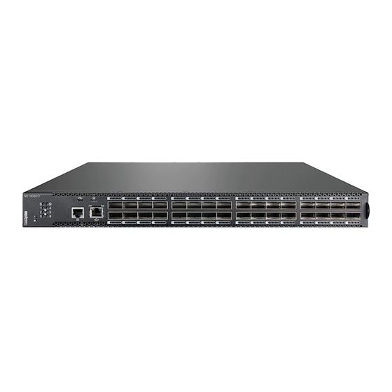
Switch Unit The NE10032 is a 1U rack-mountable GbE switch. You can mount the switch in either the horizontal or vertical orientation. The following illustrations show the features on the front and rear of the switch. Figure 1. ThinkSystem NE10032 front panel Management Panel QSFP28 Ports Figure 2. -
Page 23: Management Panel
Type B) at the same time, the RJ45 console port connection is terminated. The micro-USB console port has a higher priority than the RJ45 console port and disconnects the RJ45 console session. © Copyright Lenovo 2019 Chapter 2: Switch Components... - Page 24 If using cables other than those from the included cable kit, ensure that they are compatible with the port pin assignments shown in the following tables. Table 2. Switch micro-USB port connector pin assignments Pin Number Function No connect SIN (RS-232 Input) SOUT (RS-232 Output) No connect GND (Ground)
-
Page 25: Rj45 Management Port
Factory reset—press and hold the Reset button for more than five seconds. The switch reloads and reverts all its configuration settings to the factory defaults. © Copyright Lenovo 2019 Chapter 2: Switch Components... -
Page 26: System Status Leds
System Status LEDs The following table describes the behavior of the system status LEDs: Table 5. System status LEDs behavior State Functional Meaning Total power failure. Steady Blue An operational command has been sent to light the LED so that this device can be more readily located. Flashing Blue Service is required due to failure of the general system, - Service... -
Page 27: Micro-Usb Port
Files can be copied from the USB drive to the switch, but copying files to the NTFS formatted USB drive results in failure. For more information about using the USB drive, see the Lenovo ThinkSystem NE10032 RackSwitch Application Guide. -
Page 28: Connecting To The Switch
Connecting to the Switch Use the switch Command-Line Interface (CLI) to perform additional configuration tasks. You can access the CLI using the serial console port or management port. Using the Serial Console Port You can access the switch CLI through the serial console port on the front panel of the switch. -
Page 29: Switching Ports
25 GbE connection Flashing Amber Packet transmitting or receiving on 25 GbE connection Solid Green 10/25 GbE connection Flashing Green Packet transmitting or receiving on 10/25 GbE connection Link down or port disabled © Copyright Lenovo 2019 Chapter 2: Switch Components... -
Page 30: Rear Panel
Compatible fan options are listed in the Lenovo Networking Catalog. Fan operation and internal temperatures are monitored. If the air temperature exceeds a desired threshold, the environmental monitor displays warnings. - Page 31 The following table describes the fan module LED behavior. Table 7. Fan module status LED behavior LED State Functional Meaning Fan is on and operational. Fan module has no power. Flashing Fan speed failure. Replace the fan module. © Copyright Lenovo 2019 Chapter 2: Switch Components...
-
Page 32: Power Supply
The rear panel of the NE10032 has two bays for hot-swap power supply modules. Each power supply module has an individual IEC 320 C14 power connector. The power cord attaches to a universal grounded AC power source. Compatible power options are listed in the Lenovo Networking Catalog. Statement 5 CAUTION: The power control button on the device and the power switch on the power supply do not turn off the electrical current supplied to the device. - Page 33 There is no power switch on the NE10032 power modules; the switch powers up when power is supplied through the power cord to one or both power supplies. © Copyright Lenovo 2019 Chapter 2: Switch Components...
-
Page 34: Power Leds
Power LEDs On the front of the switch, the Power LED on the management panel indicates the general status of the power supplies. The LED flashes when only one power cord is connected, and is steady when both power cords are connected (see “System Status LEDs”... -
Page 35: Installing Ne10032 Hardware And Options
Installing the switch in one of the supported rack types “Installing the NE10032 in a Standard Equipment Rack” on page 41 “Installing the NE10032 in a Lenovo System x or Power Rack” on page 44 “Installing the NE10032 in a Lenovo iDataPlex Rack” on page 48 ... -
Page 36: Before Installing The Ne10032
Print this page and record product information below. Keep the information in a safe place for future reference. You need this information when you register the switch or open a service call with Lenovo. Table 9. Important product information... -
Page 37: Required Tools
Make sure that an adequate grounded power supply is within reach of the switch unit. Make sure that twisted-pair cable is routed away from power lines, fluorescent lighting fixtures and other sources of electrical interference. © Copyright Lenovo 2019 Chapter 3: Installing NE10032 Hardware and Options... -
Page 38: Preventing Electric Shock
Preventing Electric Shock This product does not contain any user-serviceable parts. Do not remove the cover of this device. The NE10032 AC power module is designed to work with single-phase power systems that have a grounded neutral conductor. For your safety, a power cord with a ground attachment plug is available to order for use with this product. - Page 39 3. Remove all cables from the 4. Attach signal cables to other devices. devices. 5. Connect power cords to their sources. 6. Turn ON all the power sources. © Copyright Lenovo 2019 Chapter 3: Installing NE10032 Hardware and Options...
-
Page 40: Handling Static-Sensitive Devices
Handling Static-Sensitive Devices Attention: Static electricity can damage the switch and other electronic devices. To avoid damage, keep static-sensitive devices in their static-protective packages until you are ready to install them. To reduce the possibility of electrostatic discharge, observe the following precautions: ... -
Page 41: Installing The Ne10032 In A Rack
For a standard 19-inch equipment rack, use the 2-post rack mounting brackets and screws included with the switch. Installation instructions begin on page For a Lenovo System x or Power 4-post rack, use the Lenovo Adjustable 19” 4-Post Rail Kit. This kit must be purchased separately. Installation instructions... - Page 42 Statement 26 CAUTION: Do not place any object on top of rack-mounted devices. To install the NE10032 in a standard equipment rack, complete the following steps: 1. Locate, record, and retain the product switch information in order to configure and register your product.
- Page 43 6. Initialize the switch. See Chapter 5, “Initializing the NE10032“, on page 7. If the switch is a replacement unit, set Vital Product Data (see “Configuring Vital Product Data” on page 74). © Copyright Lenovo 2019 Chapter 3: Installing NE10032 Hardware and Options...
-
Page 44: Installing The Ne10032 In A Lenovo System X Or Power Rack
Installing the NE10032 in a Lenovo System x or Power Rack This section describes how to install the NE10032 in a Lenovo System x or Power 4-post rack, using the Lenovo Adjustable 19” 4-Post Rail Kit. This kit must be purchased separately. It includes the following parts: Table 11. - Page 45 2. Attach the front mounting brackets (Item 1) to each side of the switch with M4 screws (Item 2). Torque the screws to approximately 2.0 newton-meters (Nm) ± 0.1 Nm (17.7 inch-pounds). © Copyright Lenovo 2019 Chapter 3: Installing NE10032 Hardware and Options...
- Page 46 3. From the front, slide the switch into the rack at the desired height. 4. Secure the switch to the front rack posts with M6 screws (Item 3) and either clip nuts (Item 4) or cage nuts (Item 5). Torque the screws to approximately 5.7 Nm ± 0.1 Nm (50 inch-pounds).
- Page 47 10. Initialize the switch. See Chapter 5, “Initializing the NE10032“. 11. If the switch is a replacement unit, set Vital Product Data (see “Configuring Vital Product Data” on page 74). © Copyright Lenovo 2019 Chapter 3: Installing NE10032 Hardware and Options...
-
Page 48: Installing The Ne10032 In A Lenovo Idataplex Rack
Installing the NE10032 in a Lenovo iDataPlex Rack This section describes how to install the NE10032 in a Lenovo iDataPlex rack. The iDataPlex mounting kit allows the switch to be mounted either horizontally or vertically. The kit must be purchased separately. It includes the following parts: Table 12. - Page 49 4. Secure the switch to the front rack posts with M6 screws (Item 3), and clip nuts (Item 4). Torque the screws to approximately 5.7 Nm +/- 0.1 Nm (50 inch-pounds). © Copyright Lenovo 2019 Chapter 3: Installing NE10032 Hardware and Options...
- Page 50 5. Attach the rear alignment plate (Item 6) to the rear rack posts with M6 screws (Item 3), and clip nuts (Item 4). Torque the screws to approximately 5.7 Nm +/- 0.1 Nm (50 inch-pounds). 6. If installing the 1U air-duct option, see the instruction on page 7.
-
Page 51: Installing The Air-Duct Option
If the switch has an undesirable amount of sag, it is recommended to use a 4-post mounting kit. Attention: For earthquake stability, mount the switch in a 4-post rack. © Copyright Lenovo 2019 Chapter 3: Installing NE10032 Hardware and Options... - Page 52 Statement 26 CAUTION: Do not place any object on top of rack-mounted devices. To install the 1U air-duct option in a 19” rack, complete the following steps: 1. Loosen and remove the mounting screws from both sides of the mounting rail and set them aside to reuse for securing the foam carrier in the next step.
- Page 53 5. Plug the power cords into their respective NE10032 power connectors and using tie wraps, secure the power cords to the mounting rails. Power connection Tie wraps Tie wraps Power connection © Copyright Lenovo 2019 Chapter 3: Installing NE10032 Hardware and Options...
- Page 54 6. Gently slide the air-duct unit side flanges into the card guides until the unit is seated firmly. Make sure that the foam strip is oriented on top. Foam Card guides thumbscrews Side flanges 7. Secure the air-duct unit to the air-duct brackets with the two M4 thumbscrews. NE10032 Installation Guide...
-
Page 55: Installing Port Connectors
(DAC) cables and Active Optical Cables (AOC). Note: This section covers the basic types of connectors that can be installed on the switch. We recommend you to consult the Lenovo Networking Products and Options Catalog for the full list of supported transceivers, DACs or Active Optical Cables cables. -
Page 56: Installing A Transceiver
Installing a Transceiver Note: To avoid damage to a transceiver, do not connect the cable before you install the transceiver. Statement 3 CAUTION: When laser products (such as CD-ROMs, DVD drives, fiber optic devices, or transmitters) are installed, note the following: Do not remove the covers. - Page 57 To remove a transceiver, disconnect the cable, and pull down the bail clasp, if any. This releases the transceiver. After you remove the transceiver, cover it using its safety cap. © Copyright Lenovo 2019 Chapter 3: Installing NE10032 Hardware and Options...
- Page 58 NE10032 Installation Guide...
-
Page 59: Removing And Replacing Components
Removing the switch from one of the supported rack types “Removing the NE10032 from a Standard Equipment Rack” on page 67 “Removing the NE10032 from a Lenovo System x or Power Rack” on page 68 “Removing the NE10032 from a Lenovo iDataPlex Rack” on page 71 ... -
Page 60: Removing Port Transceivers
Removing Port Transceivers Statement 3 CAUTION: When laser products (such as CD-ROMs, DVD drives, fiber optic devices, or transmitters) are installed, note the following: Do not remove the covers. Removing the covers of the laser product could result in exposure to hazardous laser radiation. There are no serviceable parts inside the device. -
Page 61: Removing And Replacing A Power Supply Module
For proper airflow when operating the switch with only one power supply module, the empty power supply bay must be closed by a blank power filler plate. © Copyright Lenovo 2019 Chapter 4: Removing and Replacing Components... -
Page 62: Removing The Power Supply Module
Removing the Power Supply Module Statement 5 CAUTION: The power control button on the device and the power switch on the power supply do not turn off the electrical current supplied to the device. The device also might have more than one power cord. To remove all electrical current from the device, ensure that all power cords are disconnected from the power source. -
Page 63: Replacing The Power Supply Module
Connect and disconnect cables as described in the following table when you install, move, or open covers on this product or attached devices. © Copyright Lenovo 2019 Chapter 4: Removing and Replacing Components... - Page 64 To Connect: To Disconnect: 1.Turn OFF all power sources and 1.Turn OFF all power sources and equipment that is to be attached to equipment that is to be attached to this product. this product. For ac systems, remove all power ...
-
Page 65: Removing And Replacing A Fan Module
“Getting Help and Technical Assistance“ to help you gather all the required information that is necessary to return a component. After you remove the component, securely pack the component for shipping. © Copyright Lenovo 2019 Chapter 4: Removing and Replacing Components... -
Page 66: Replacing The Fan Module
Replacing the Fan Module To replace a hot-swap fan module, complete the following steps: 1. Select an empty fan module bay on the rear of the switch. If the target bay is covered by a blank fan filler plate, loosen the retainer screw and slide the filler plate out of the slot. -
Page 67: Removing The Ne10032 From A Standard Equipment Rack
5. Loosen and remove the M4 screws attaching the mounting bracket on each side of the switch. 6. If replacing the unit with another NE10032, see “Replacing the NE10032” on page © Copyright Lenovo 2019 Chapter 4: Removing and Replacing Components... -
Page 68: Removing The Ne10032 From A Lenovo System X Or Power Rack
Removing the NE10032 from a Lenovo System x or Power Rack This section describes how to remove the NE10032 from a Lenovo System x or Power 4-post rack. To remove the NE10032 from a System x or Power rack, complete the following steps: 1. - Page 69 5. Slide the rear mounting brackets out of their slots in the front mounting brackets. 6. Loosen and remove the M6 screws and clip nuts (or cage nuts) connecting the front mounting brackets to the front rack posts. © Copyright Lenovo 2019 Chapter 4: Removing and Replacing Components...
- Page 70 7. Slide the NE10032 unit out of the rack. 8. Loosen and remove the M4 screws that attach the front mounting brackets to each side of the switch. 9. If replacing the unit with another NE10032, see “Replacing the NE10032” on page NE10032 Installation Guide...
-
Page 71: Removing The Ne10032 From A Lenovo Idataplex Rack
Removing the NE10032 from a Lenovo iDataPlex Rack This section describes how to remove the NE10032 from a Lenovo iDataPlex rack. To remove the NE10032 from an iDataPlex rack, complete the following steps: 1. Disconnect all external cables. 2. If the 1U air-duct option has been installed, remove it as described in “Removing... - Page 72 5. Slide the switch out of the rack. 6. Loosen and remove the M4 screws that attach front and rear mounting brackets to each side of the switch. 7. If replacing the unit with another NE10032, see “Replacing the NE10032” on page NE10032 Installation Guide...
-
Page 73: Removing The Air-Duct Option
Removing the Air-Duct Option The NE10032 supports an optional 1U air duct to maximize air flow conditions in a Lenovo Power Systems Group rack. To remove an installed 1U air-duct option from a 19” rack, complete the following steps. 1. Loosen the M4 thumbscrews securing the air-duct unit to the mounting brackets. -
Page 74: Replacing The Ne10032
Replacing the NE10032 Preparing and Returning the NE10032 If replacing the NE10032, remove all associated components and options according to the instructions in this chapter. Remove and retain clips, cords, cables, modules, caps or blanks, air-duct option (if installed), and any mounting hardware. These items can then be reinstalled on the replacement unit. - Page 75 System Management MAC : 3C:2C:99:F8:91:40 For more information about using the switch interface, see the Application Guide and Command Reference for the NE10032 and its corresponding Lenovo Network Operating System and firmware version. © Copyright Lenovo 2019 Chapter 4: Removing and Replacing Components...
- Page 76 NE10032 Installation Guide...
-
Page 77: Initializing The Ne10032
The device also might have more than one power cord. To remove all electrical current from the device, ensure that all power cords are disconnected from the power source. © Copyright Lenovo 2019... -
Page 78: System Status Leds
System Status LEDs The following LEDs on the switch front panel indicate the overall system status: Power - Steady green if the power supply modules are on and operational, flashing green in case of a power supply failure, or off in case of a total power supply failure. -
Page 79: Logging Into The Switch
Notes:If the switch has already started prior to your connection, you may need to press Enter to display the password prompt. After successfully logging into the switch, the following CLI prompt is displayed: NOS 10.8.5.0 Lenovo ThinkSystem NE10032 RackSwitch, Oct 23 01:27:54 2018 NE10032> © Copyright Lenovo 2019... -
Page 80: Changing The Default Network Administrator Password
Changing the Default Network Administrator Password After logging onto the switch for the first time, a screen prompt appears requesting you to change the default network administrator password. You are required to change your default 'admin' user password immediately Changing password for admin. Current Administrator password: Choose a strong password (Min 8 chars, at least 1 uppercase, 1 lowercase, 1 number etc.) -
Page 81: Default Configuration Files
Enter y at the prompt to confirm the erasing process and then reload the switch: NE10032# reload Using Rescue Mode available from the GRUB Menu. For more details, see “The GRUB Menu” on page © Copyright Lenovo 2019 Chapter 5: Initializing the NE10032... -
Page 82: Configuring The Management Interface For Remote Access
Configuring the Management Interface for Remote Access To manage the switch remotely using Telnet or SNMP you must first configure the management interface. You can use DHCP to automatically configure the interface (enabled by default), or you can manually configure the following IP parameters: ... -
Page 83: Out-Of-Band Management Interface Configuration
NE10032# configure [terminal] NE10032(config)# 3. Configure the in-band management IP address: NE10032(config)# interface vlan 1 NE10032(config-if)# ip address 10.254.87.6/24 NE10032(config-if)# exit NE10032(config)# 4. Configure the in-band default gateway: NE10032(config)# ip route 0.0.0.0/0 205.21.17.1 © Copyright Lenovo 2019 Chapter 5: Initializing the NE10032... -
Page 84: Updating Firmware
Updating Firmware If firmware updates are available, you can download them from the Lenovo website. The switch might have features that are not described in the documentation that comes with the switch, and the documentation might be updated occasionally to include information about those features, or technical updates might be available to provide additional information that is not included in the switch documentation. -
Page 85: The Grub Menu
The GRUB Menu The Lenovo ThinkSystem NE10032 RackSwitch does not use a Boot Management menu. Instead, all images are preloaded, and all booting options, such as switching boot images, are included in the GNU GRUB bootloader. To boot CNOS or switch images on the NE10032: 1. -
Page 86: Rescue Mode
Rescue Mode The Rescue Mode option allows you to recover from a failed firmware or boot image upgrade using TFTP or a USB drive. To enter Rescue Mode, select Recovery Mode in the GRUB menu. The following menu appears. Entering Rescue Mode. Please select one of the following options: T) Configure networking and tftp download an image U) Install image from USB stick... -
Page 87: Troubleshooting
If you have problems accessing the switch or working with the firmware, see the NE10032 Application Guide and/or the Command Reference. For information about calling Lenovo for service, see Appendix A, “Getting Help and Technical Assistance“. -
Page 88: System Led Is Not Lit
System LED Is Not Lit Symptom: The power supply LED is not lit. Solution: Check the power supply to make sure that there is a proper connection to the power source. Make sure that power is available from the power source. NE10032 Installation Guide... -
Page 89: Port Link Led Is Not Lit
Solution 2: Check the cables that connect the port to the other device. Make sure that they are connected correctly. Make sure that you are using the correct cable type. © Copyright Lenovo 2019 Chapter 6: Troubleshooting... -
Page 90: Temperature Sensor Warning
Temperature Sensor Warning Symptom: A temperature warning is displayed on the management console. Solution: Make sure that the air circulation vents on the front, back, and sides of the switch are free from obstruction by cables, panels, rack frames, or other materials. Make sure that all cooling fans inside the switch are running. -
Page 91: Switch Does Not Initialize (Boot)
Symptom: All the switch LEDs stay on, and the command prompt is not displayed on the console. Solution: The operating system might be damaged. Use the console port to perform a serial upgrade of the switch firmware. See the Command Reference. © Copyright Lenovo 2019 Chapter 6: Troubleshooting... - Page 92 NE10032 Installation Guide...
-
Page 93: Getting Help And Technical Assistance
Lenovo to assist you. Use this information to obtain additional information about Lenovo and Lenovo products, and determine what to do if you experience a problem with your Lenovo system or optional device. Note: This section includes references to IBM web sites and information about obtaining service. - Page 94 You can solve many problems without outside assistance by following the troubleshooting procedures that Lenovo provides in the online help or in the Lenovo product documentation. The Lenovo product documentation also describes the diagnostic tests that you can perform. The documentation for most systems, operating systems, and programs contains troubleshooting procedures and explanations of error messages and error codes.
-
Page 95: Notices
Web sites. The materials at those Web sites are not part of the materials for this Lenovo product, and use of those Web sites is at your own risk. - Page 96 Any performance data contained herein was determined in a controlled environment. Therefore, the result obtained in other operating environments may vary significantly. Some measurements may have been made on development-level systems and there is no guarantee that these measurements will be the same on generally available systems.
-
Page 97: Trademarks
Trademarks Lenovo, the Lenovo logo, Flex System, System x, NeXtScale System, and X-Architecture are trademarks of Lenovo in the United States, other countries, or both. Intel and Intel Xeon are trademarks of Intel Corporation in the United States, other countries, or both. -
Page 98: Important Notes
(TBW). A device that has exceeded this limit might fail to respond to system-generated commands or might be incapable of being written to. Lenovo is not responsible for replacement of a device that has exceeded its maximum guaranteed number of program/erase cycles, as documented in the Official Published Specifications for the device. -
Page 99: Open Source Information
Lenovo. This offer is valid to anyone in receipt of this Lenovo Switch. You may send your request in writing to the address below accompanied by a check or money... -
Page 100: Recycling Information
Recycling Information Lenovo encourages owners of information technology (IT) equipment to responsibly recycle their equipment when it is no longer needed. Lenovo offers a variety of programs and services to assist equipment owners in recycling their IT products. For information on recycling Lenovo products, go to: https://www.lenovo.com/recycling... -
Page 101: Particulate Contamination
If Lenovo determines that the levels of particulates or gases in your environment have caused damage to the device, Lenovo may condition provision of repair or replacement of devices or parts on implementation of appropriate remedial measures to mitigate such environmental contamination. -
Page 102: Telecommunication Regulatory Statement
This product may not be certified in your country for connection by any means whatsoever to interfaces of public telecommunications networks. Further certification may be required by law prior to making any such connection. Contact a Lenovo representative or reseller for any questions. NE10032 Installation Guide... -
Page 103: Electronic Emission Notices
Properly shielded and grounded cables and connectors must be used to meet FCC emission limits. Lenovo is not responsible for any radio or television interference caused by using other than recommended cables and connectors or by unauthorized changes or modifications to this equipment. -
Page 104: European Union - Compliance To The Electromagnetic Compatibility Directive
Grenzwerte der Klasse A der Norm gemäß Richtlinie. Um dieses sicherzustellen, sind die Geräte wie in den Handbüchern beschrieben zu installieren und zu betreiben. Des Weiteren dürfen auch nur von der Lenovo empfohlene Kabel angeschlossen werden. Lenovo übernimmt keine Verantwortung für die Einhaltung der Schutzanforderungen, wenn das Produkt ohne Zustimmung... -
Page 105: Japan Vcci Class A Statement
Dieses Gerät ist berechtigt, in Übereinstimmung mit dem Deutschen EMVG das EG-Konformitätszeichen - CE - zu führen. Verantwortlich für die Konformitätserklärung nach Paragraf 5 des EMVG ist die Lenovo (Deutschland) GmbH, Meitnerstr. 9, D-70563 Stuttgart. Informationen in Hinsicht EMVG Paragraf 4 Abs. (1) 4: Das Gerät erfüllt die Schutzanforderungen nach EN 55024 und EN 55022 Klasse A. -
Page 106: Korea Communications Commission (Kcc) Statement
Korea Communications Commission (KCC) Statement This is electromagnetic wave compatibility equipment for business (Type A). Sellers and users need to pay attention to it. This is for any areas other than home. Russia Electromagnetic Interference (EMI) Class A statement People’s Republic of China Class A electronic emission statement Taiwan Class A compliance statement NE10032 Installation Guide... -
Page 107: Taiwan Bsmi Rohs Declaration
Note 2: “?” indicates that the percentage content of the restricted substance does not exceed the reference per- centage value of presence. 備考 3. 〝-〞係指該項限用物質為排除項目。 Note 3: The “–” indicates that the restricted substance corresponds to the exemption. © Copyright Lenovo 2019 Appendix B: Notices... - Page 108 NE10032 Installation Guide...
-
Page 109: Technical Specifications
Appendix C. Technical Specifications The NE10032 technical specifications are described in the following sections. © Copyright Lenovo 2019... -
Page 110: Physical Characteristics
Physical Characteristics The physical characteristics of the NE10032 are listed in the following table. Table 14. Physical characteristics Specification Physical characteristics Dimensions (H x W x D) 4.4 x 43.9 x 48.7 cm (1.73 x 17.3 x 19.2 in) Weight 11.5 kg (25 lb) maximum Airflow Available options for rear to front,... -
Page 111: Environmental Specifications
Relative humidity (non-condensing), 5 to 95% storage Altitude, operating -60 m to +2000 m (-196.85 to +6561.7 ft) Altitude, storage Acoustic noise Less than 90 dB Heat dissipation 722.69 BTU/h (typical) 1277.85 BTU/h (maximum) © Copyright Lenovo 2019 Appendix C: Technical Specifications... -
Page 112: Power Specifications
Power Specifications The power specifications for the NE10032 are listed in the following table. Table 16. NE10032 AC power specifications Specification Measurement Number of power supplies 2 (1+1 load sharing/redundant) AC-input frequency (universal) 50–60 Hz AC-input voltage (universal) 100–240 VAC AC inrush current 4.64 A @ 120 VAC (typical) 10.56 A @ 230 VAC (typical) -
Page 113: Switching Performance
Note: The specific features supported on your switch, as well as some capacity and performance characteristics, depend on the specific firmware installed. For more information, see the Application Guide and Command Reference for your specific switch and its installed firmware. © Copyright Lenovo 2019 Appendix C: Technical Specifications... - Page 114 NE10032 Installation Guide...
Need help?
Do you have a question about the ThinkSystem NE10032 RackSwitch and is the answer not in the manual?
Questions and answers