Table of Contents
Advertisement
Quick Links
Advertisement
Table of Contents

Related Manuals for Lenovo ThinkSystem NE2552E


Summary of Contents for Lenovo ThinkSystem NE2552E
- Page 1 Lenovo ThinkSystem NE2552E Flex Switch Installation Guide...
- Page 2 Important Product Information— Before using this information and the product it supports, read Appendix B, “Notices” on page 57 of this manual. Also read the product Warranty Information document, the Important Notices document, the Safety Information document, the License Agreement for Machine Code (LAMC) document, and the Environmental Notices and User Guide document located at Lenovo ThinkSystem, System x, ThinkServer, and Storage product documentation. First Edition (May 2018) © Copyright Lenovo 2018 Portions © Copyright IBM Corporation 2014. LIMITED AND RESTRICTED RIGHTS NOTICE: If data or software is delivered pursuant a General Services Administration “GSA” contract, use, reproduction, or disclosure is subject to restrictions set forth in Contract No. GS‐35F‐05925. Lenovo and the Lenovo logo are trademarks of Lenovo in the United States, other countries, or both.
-
Page 3: Table Of Contents
......5 Safety Statements . . . . . . . . . . . . . . . . . . . . . . . . . . . . 7 UL Regulatory Information . . . . . . . . . . . . . . . . . . . . . . 8 Chapter 1. The ThinkSystem NE2552E Flex Switch ... 9 Documentation . . . . . . . . . . . . . . . . . . . . . . . . . . . . .11 About this Installation Guide . . . . . . . . . . . . . . . . . . . . .11 Notices and Statements in this Document . . . . . . . . . . . . . . .11... - Page 4 Federal Communications Commission (FCC) Statement . . . . . . . . . 64 Industry Canada Class A Emission Compliance Statement . . . . . . . . 64 Avis de Conformité à la Réglementation dʹIndustrie Canada . . . . . . . 64 Australia and New Zealand Class A Statement . . . . . . . . . . . . . 64 European Union ‐ Compliance to the Electromagnetic Compatibility Directive Germany Class A Statement . . . . . . . . . . . . . . . . . . . . . 65 VCCI Class A Statement . . . . . . . . . . . . . . . . . . . . . . . 66 Japan Electronics and Information Technology Industries Association (JEITA) Statement. . . . . . . . . . . . . . . . . . . . . . . . . . 67 Korea Communications Commission (KCC) Statement. . . . . . . . . . 67 Russia Electromagnetic Interference (EMI) Class A Statement . . . . . . . 67 People’s Republic of China Class A Electronic Emission Statement . . . . 67 Taiwan BSMI RoHS Declaration . . . . . . . . . . . . . . . . . . . 68 Taiwan Class A Compliance Statement . . . . . . . . . . . . . . . . 68 Lenovo ThinkSystem NE2552E Flex Switch: Installation Guide...
-
Page 5: Safety Information
Safety Information Before installing this product, read the Safety Information. Antes de instalar este produto, leia as Informações de Segurança. Prije instalacije ovog produkta obavezno pročitajte Surgonosne Upute. Před instalací tohoto produktu si přečtěte příručku bezpečnostních instrukcí. Læs sikkerhedsforskrifterne, før du installerer dette produkt. Lees voordat u dit product installeert eerst de veiligheidsvoorschriften. Ennen kuin asennat tämän tuotteen, lue turvaohjeet kohdasta Safety Information. Avant dʹinstaller ce produit, lisez les consignes de sécurité. Vor der Installation dieses Produkts die Sicherheitshinweise lesen.’ Πριν εγκαταστήσετε το προϊόν αυτό, διαβάστε τις Πληροφορίες ασφαλείας (safety information). A termék telepítés előtt olvassa el a Biztonsági előírásokat! Prima di installare questo prodotto, leggere le Informazioni sulla Sicurezza. Πред да инсталира овој продукт, прочитајте информацијата за безбедност. Les sikkerhetsinformasjonen (Safety Information) før du installerer dette produktet. Przed zainstalowaniem tego produktu, należy zapoznać się z książką “Informacje dotyczace bezpieczeństwa” (Safety Information). Antes de instalar este produto, leia as Informações sobre Segurança. Перед установкой продукта прочтитe инcтрyкции по тexникe безопасности. Pred inštaláciou tohto zariadenia si prečítajte Bezpečnostné predpisy. © Copyright Lenovo 2018 : Safety Information... - Page 6 Pred namestitvijo tega proizvoda preberite Varnostne informacije. Antes de instalar este producto, lea la información de seguridad. Läs säkerhetsinformationen innan du installerar den här produkten. Bu ürünü kurmadan önce güvenlik bilgilerini okuyun. Youq mwngz yungh canjbinj neix gaxgonq, itdingh aeu doeg aen canjbinj soengq cungj vahgangj ancien suisik. Lenovo ThinkSystem NE2552E Flex Switch: Installation Guide...
-
Page 7: Safety Statements
To avoid a shock hazard: Do not connect or disconnect any cables or perform installation, maintenance, or reconfiguration of this product during an electrical storm. Connect all power cords to a properly wired and grounded electrical outlet. Connect to properly wired outlets any equipment that will be attached to this product. When possible, use one hand only to connect or disconnect signal cables. Never turn on any equipment when there is evidence of fire, water, or structural damage. Disconnect the attached power cords, telecommunications systems, networks, and modems before you open the device covers, unless instructed otherwise in the installation and configuration procedures. Connect and disconnect cables as described in the following table when installing, moving, or opening covers on this product or attached devices. To Connect: To Disconnect: 1. Turn everything OFF. 1. Turn everything OFF. 2. First, attach all cables to devices. 2. First, remove power cords from outlet. 3. Attach signal cables to connectors. 3. Remove signal cables from connectors. 4. Attach power cords to outlet. 4. Remove all cables from devices. 5. Turn device ON. © Copyright Lenovo 2018 : Safety Information... -
Page 8: Ul Regulatory Information
Laser Klass 1 Luokan 1 Laserlaite Appareil À Laser de Classe 1 Statement 25 CAUTION: This product contains a Class 1M laser. Do not view directly with optical instruments. UL Regulatory Information This device is for use only with listed Lenovo Flex System Enterprise Chassis. Lenovo ThinkSystem NE2552E Flex Switch: Installation Guide... -
Page 9: Chapter 1. The Thinksystem Ne2552E Flex Switch
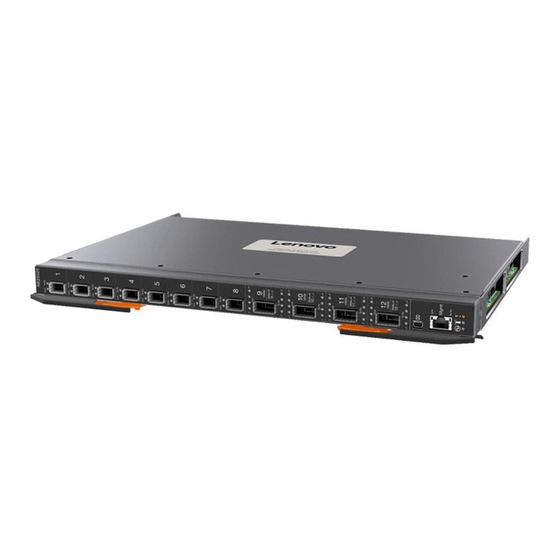
Chapter 1. The ThinkSystem NE2552E Flex Switch This Installation Guide provides information about the Lenovo® Flex System™ ThinkSystem NE2552E Flex Switch (referred to as NE2552E or “switch” throughout this document). Figure 1. The NE2552E SFP28 module ports QSFP28 module ports RS-232 mini serial port (console access) RJ-45 external management port Switch status LEDs Note: The illustrations in this document might differ slightly from your hardware. © Copyright Lenovo 2018... - Page 10 The Lenovo ThinkSystem NE2552E Flex Switch supports a 10G/25G/50G flex server connection and is capable of 10G, 25G, 50G, and 100G uplink connections. The NE2552E supports eight 25G SFP28 ports, four 100G QSFP28 ports, and one 10/100/1000 Base‐T external management port on the faceplate as well as 28 25GBase‐KR internal links to the 14 IT Elements (commonly known as blade server or flex server). The internal links are configurable and support line rates of 10GBase‐KR and 25GBase‐KR with support for 2x25G or 1x50G to an ITE Network Adapter using physical/KR lane multiplexor. The external facing SFP28 ports support 8x10G/25G line rates. The 100G QSFP ports are configurable as 100G, 2x50G, or 4x10G/25G ports. The NE2552E provides support for the following: A combination of either 28x10G/25G or 14x50G ports internally. 8x10G/25G SFP28 ports plus 4x100G QSFP+ ports, and 10/100/1000 Base‐T management port externally. The 100G ports are capable of 4x10G/25G, or 2x50G breakout configurations. In addition to port flexibility, you can manage and configure the NE2552E through the following interfaces: A Secure Shell (SSH) version 2 or Telnet connection to the embedded Command‐Line Interface (CLI) A terminal emulation program connection to the serial port interface A network management application using Simple Network Management Protocol (SNMP) Lenovo ThinkSystem NE2552E Flex Switch: Installation Guide...
-
Page 11: Documentation
Notices and Statements in this Document The caution and danger statements in this document are also in the multilingual Safety Information document, which is located at Lenovo System x, ThinkServer and Storage product documentation. Each statement is numbered for reference to the corresponding statement in the Safety Information document. The following notices and statements are used in this document: Note: These notices provide important tips, guidance, or advice. Important: These notices provide information or advice that might help you avoid inconvenient or problem situations. Attention: These notices indicate potential damage to programs, devices, or data. An attention notice is placed just before the instruction or situation in which damage could occur. Caution: These statements indicate situations that can be potentially hazardous to you. A caution statement is placed just before the description of a potentially hazardous procedure step or situation. Danger: These statements indicate situations that can be potentially lethal or extremely hazardous to you. A danger statement is placed just before the description of a potentially lethal or extremely hazardous procedure step or situation. © Copyright Lenovo 2018 Chapter 1: The ThinkSystem NE2552E Flex Switch... -
Page 12: Related Documentation
Related Documentation Additional or updated product documents may be available from the Lenovo website. Such documents may cover features not described in the original documentation that comes with the switch, or may include technical updates or corrections. You can obtain up‐to‐date information on the Lenovo support website: http://support.lenovo.com/ Note: Changes are made periodically to the Lenovo website. Procedures for locating firmware and documentation might vary slightly from what is described in this document. For information about switch hardware and firmware features, specifications, and standards, including their configuration, see the Application Guide for your specific switch and its installed firmware. For information about the switch information, statistics, and individual configuration parameters, see the Command Reference for your specific switch and its installed firmware. For a list of compatible switch components and options (such as rack‐mounting kits, modules, cords, and cables), see the Lenovo Networking Catalog. See the documentation that came with your Lenovo chassis for information about the environmental conditions and specifications that are supported by the system. Lenovo ThinkSystem NE2552E Flex Switch: Installation Guide... -
Page 13: Chapter 2. Installing And Removing The Ne2552E
Chapter 2. Installing and Removing the NE2552E This chapter provides instructions for installing and removing the NE2552E in the Lenovo Flex System chassis. See the documentation for your Lenovo Flex System chassis for information about I/O bay locations and the components that can be installed in them that is specific to your Lenovo Flex System chassis type. The following illustration shows an example of a Lenovo Flex System chassis (rear‐view) with the I/O bays identified. Figure 2. Flex System chassis I/O bays. I/O Module I/O Module I/O Module I/O Module Bay 1 Bay 3 Bay 2 Bay 4 A Lenovo Flex System network adapter must be installed in each compute node with which you want to communicate. To enable the switch to communicate with a compute node, at least one switch must be installed in the Lenovo Flex System chassis. For details about network adapter installation, configuration, and use, see the documentation that comes with the Lenovo Flex System network adapter. Installing a second switch enables a redundant path and a separate connection from the compute node to the external Ethernet network. The Lenovo Flex System chassis supports a maximum of four NE2552E modules. The Lenovo Flex System chassis supports a maximum of twenty‐eight network adapters. © Copyright Lenovo 2018... - Page 14 Note: I/O bays 1 and 2 support any standard Lenovo Flex System switch or pass‐thru module. When you install an I/O network adapter in the I/O Expansion 1 Connector on the compute node, these I/O bays support any switch with the same type of network interface that is used by the corresponding network adapter. I/O bays 3 and 4 support any standard Lenovo Flex System switch or pass‐thru module. When you install an I/O network adapter in the I/O Expansion 2 Connector on the compute node, these I/O bays support any switch with the same type of network interface that is used by the corresponding network adapter. The compute nodes or Lenovo Flex System chassis that are described or shown in this document might be different from your compute node or Lenovo Flex System chassis. For additional information, see the documentation that comes with your Lenovo Flex System chassis. When the switch is installed in a Lenovo Flex System chassis, by default the internal ports operate at 10/25 Gigabits per second (Gbps) and the external ports operate at 10/25 Gbps and 50/100 Gbps, depending on the port type and installed transceiver modules. Lenovo ThinkSystem NE2552E Flex Switch: Installation Guide...
-
Page 15: Before Installing The Ne2552E
Before Installing the NE2552E Attention: Product information is required in order to register your NE2552E, update its firmware, place a service call, or replace the unit. Some of the product information labels may be hidden from view once the NE2552E is installed. To prevent the need to remove the switch in order to read required product information, locate and record the information shown on Table 1 on page 16 prior to installation. An example of the product information labels is shown as follows: Figure 3. Sample product labels from the switch Note: These examples are to help locate and identify the information labels. The actual labels and information for your specific switch may differ. The identification labels on the NE2552E contain the serial number and part number of the switch. These labels also include the Media Access Control (MAC) address (on the uppermost handle) of the switch. Though helpful, the MAC address is not required for opening a service call. © Copyright Lenovo 2018 Chapter 2: Installing and Removing the NE2552E... -
Page 16: Installation Guidelines
Read the safety information that begins on page 5, “Handling Static‐Sensitive Devices” on page 17, and the safety statements in the Lenovo Flex System chassis documentation. This information provides a safe working environment. Observe good housekeeping in the area where you are working. Place removed covers and other parts in a safe place. Blue on a component indicates touch points, where you can grip the component to remove it from or install it in the compute node or Lenovo Flex System chassis, open or close a latch, and so on. Orange on a component or an orange label on or near a component on the switch, compute node, or Lenovo Flex System chassis indicates that the component can be hot‐swapped, which means that if the Lenovo Flex System chassis and operating system support hot‐swap capability, you can remove or install the component while the Lenovo Flex System chassis is running. (Orange can also indicate touch points on hot‐swap components.) See the instructions for removing or installing a specific hot‐swap component for any additional procedures that you might have to perform before you remove or install the component. You do not have to turn off the Lenovo Flex System chassis to install or replace any of the hot‐swap modules on the front or rear of the Lenovo Flex System chassis. When you install the switch in the Lenovo Flex System chassis, you must also install a compatible I/O network adapter in the compute node to support the switch. When you are finished working on the compute node or Lenovo Flex System chassis, reinstall all safety shields, guards, labels, and ground wires. Lenovo ThinkSystem NE2552E Flex Switch: Installation Guide... -
Page 17: System Reliability Guidelines
Limit your movement. Movement can cause static electricity to build up around you. The use of a grounding system is recommended. For example, wear an electrostatic‐discharge wrist strap, if one is available. Handle the device carefully, holding it by its edges or its frame. Do not touch solder joints, pins, or exposed printed circuitry. Do not leave the device where others can handle and damage it. While the device is still in its static‐protective package, touch it to an unpainted metal part of any unpainted metal surface on a grounded rack component in the rack in which you are installing the device, for at least two seconds. This drains static electricity from the package and from your body. Remove the device from its package and install it directly into the switch without setting it down. If it is necessary to set down the device, put it back into its static‐protective package. Do not place the device on a switch cover or on a metal surface. Take additional care when you handle devices during cold weather. Heating reduces indoor humidity and increases static electricity. Some types of Lenovo Flex System chassis come with electrostatic discharge (ESD) connectors. If your unit is equipped with an ESD connector, see the documentation that comes with the Lenovo Flex System chassis for using the ESD connector. © Copyright Lenovo 2018 Chapter 2: Installing and Removing the NE2552E... -
Page 18: Installing The Ne2552E
1 and 2, and I/O modules of the same type in bays 3 and 4 of the chassis. To install the switch, complete the following steps. Read the safety information that begins on page 5 and “Installation Guidelines” on page 2. Select I/O bay in which to install the switch. Note: For details about I/O bay requirements and bay locations, see the documentation for the Lenovo Flex System chassis. 3. Remove the filler module from the selected bay. Store the filler module for future use. 4. If you have not already done so, touch the static‐protective package that contains the switch to an unpainted metal surface of the Lenovo Flex System chassis or an unpainted metal surface on any other grounded rack‐component for at least 2 seconds. 5. Remove the switch from its static‐protective package. 6. Make sure that the release levers on the switch are in the open position (perpendicular to the switch). 7. Slide the switch into the applicable I/O bay until it stops. 8. Push the release levers on the front of the switch to the closed position. After you insert and lock the switch, it is turned on (there may be a slight delay), and a Power‐On Self‐Test (POST) occurs to verify that the switch is operating correctly. Lenovo ThinkSystem NE2552E Flex Switch: Installation Guide... - Page 19 Note: The switch may take up to two minutes to complete the POST. During POST, the Power LED continuously flashes. Once POST has successfully completed, the Power LED remains on and the Error LED is off. 9. Make sure that LEDs on the switch indicate that it is operating correctly (see “Information LEDs” on page 34). If you have another switch to install, repeat Step 3 through Step 9; otherwise, go to the next step. 11. Install any port transceiver modules or Direct‐Attach Cables (DACs) needed for the switch. For information and instructions, see “Connecting Switch Ports” on page 21 and the documentation that comes with the transceiver modules or DACs. © Copyright Lenovo 2018 Chapter 2: Installing and Removing the NE2552E...
-
Page 20: Removing Or Replacing The Switch
To replace the switch, complete the following steps. Read the safety information that begins on page 5, and “Installation Guidelines” on page 2. Detach any cables that are attached to the switch you will be removing. Note: Detaching cables from the switch ports disrupts the network connection from the switch to any connected external devices. If you plan to replace the switch with another switch, you can reuse the existing cables, provided they remains securely attached to the network. 3. Pull the release latches out from the switch. The switch moves out of the bay approximately 0.6 cm (0.25 inch). 4. Slide the switch out of the bay and set it aside in a safe, static‐free location. 5. Place either another switch or a filler module in the bay. Note: Complete this step within 1 minute. For more information, see “Installing the NE2552E” on page 6. If you placed the switch in the bay, reconnect the ports that you disconnected in Step 2 and attach any additional cables that are required by the switch. For additional information about connecting ports, see “Connecting Switch Ports” on page 21, and also the documentation that comes with the port transceiver modules, DACs, cables, and the optional network devices to which the cables have been connected. Lenovo ThinkSystem NE2552E Flex Switch: Installation Guide... -
Page 21: Connecting Switch Ports
The switch supports MSA‐compliant copper DACs, up to 5 m (16.5 ft.) in length. The Serial Console Port This section discusses connecting and disconnecting the serial console cable. Connecting the Serial Console Cable To use the serial console, connect a serial cable to the RS‐232 serial console port of the switch and the other end of the cable to the console device. Note: You must use one of the two cables in the Serial Access Cable option. If your console device uses a standard RS‐232 DB9 connector, attach the included mini‐USB‐to‐DB9 serial cable. Otherwise, if your console device uses an RJ‐45 connector, attach the included mini‐USB‐to‐RJ‐45 serial cable and a user‐supplied RJ‐45 adapter cable. Your adapter cable depends on the pin out required by your console device. Pin out of the mini‐USB‐to‐RJ‐45 cable is as follows: Table 2. Pin out for the included mini‐USB‐to‐RJ‐45 cable PIN # Function Direction Not connected © Copyright Lenovo 2018 Chapter 2: Installing and Removing the NE2552E... -
Page 22: The Rj-45 Management Port
Pin out for the included mini‐USB‐to‐RJ‐45 cable PIN # Function Direction Not connected Not connected Not connected For additional information, see “Accessing the Switch Through the Serial‐Port Interface” on page Disconnecting the Serial Console Cable To disconnect the serial console cable, grasp the connector and gently pull the cable from the switch. The RJ-45 Management Port Connecting RJ-45 Cables RJ‐45 cables can be connected to the to external management port, and also to SFP+ ports that have legacy 1000BASE‐T SFP transceiver modules. To connect the RJ‐45 connector to the switch, push the RJ‐45 cable connector into the port connector until it clicks into place. Disconnecting RJ-45 Cables To disconnect the RJ‐45 cable, squeeze the release tab and gently pull the cable connector out of the switch connector. Lenovo ThinkSystem NE2552E Flex Switch: Installation Guide... -
Page 23: Handling Transceiver Modules
Use of controls or adjustments or performance of procedures other than those specified herein might result in hazardous radiation exposure. DANGER Some laser products contain an embedded Class 3A or Class 3B laser diode. Note the following. Laser radiation when open. Do not stare into the beam, do not view directly with optical instruments, and avoid direct exposure to the beam. Class 1 Laser Product Laser Klasse 1 Laser Klass 1 Luokan 1 Laserlaite Appareil À Laser de Classe 1 © Copyright Lenovo 2018 Chapter 2: Installing and Removing the NE2552E... -
Page 24: Sfp28 Ports
Read the safety information that begins on page 5 and “Installation Guidelines” on page 2. If you have not already done so, touch the static‐protective package that contains the SFP+ or SFP28 module to an unpainted metal surface of the Lenovo Flex System chassis or an unpainted metal surface on any other grounded rack component in the rack in which you are installing the switch for at least 2 seconds. Read the information in “Handling Transceiver Modules” on page 4. Remove the SFP+ or SFP28 module from its static‐protective package. 5. If a protective cap is installed in the switch SFP28 port where you are installing the SFP+ or SFP28 module, remove the cap and store it in a safe place. 6. Remove the protective cap from the SFP+ or SFP28 module and store it in a safe place. Attention: To avoid damage to the cable or the SFP+ or SFP28 module, make sure that you do not connect the fiber optic cable before the SFP+ or SFP28 module is installed in the switch port. 7. Insert the SFP28 or SFP+ module into the switch SFP28 port until it clicks into place. SFP28 port Protective cap SFP+ or SFP28 module Connect the fiber optic cable (see “Attaching a Fiber Optic Cable” on page 25) and any cables that you disconnected earlier. Lenovo ThinkSystem NE2552E Flex Switch: Installation Guide... - Page 25 Do not put excess weight on the cable at the connection point. Make sure that the cable is well supported. To connect the fiber‐optic cable to the SFP+ or SFP28 module, complete the following steps. 1. Remove the protective caps from the end of the fiber optic cable. Fiber-optic cable Protective cap 2. Gently slide the fiber optic cable into the SFP+ or SFP28 module until it clicks into place. 3. Check the LEDs on the switch. When the switch is operating correctly, the green link LED is lit. For information about the status of the switch LEDs, see “Locating the Information Panels, LEDs, and External Ports” on page Disconnecting a Fiber Optic Cable To disconnect the fiber optic cable from an SFP+ or SFP28 module, complete the following steps: 1. Squeeze the release tabs and gently pull the fiber optic cable from the module. 2. Replace the protective caps on the ends of the fiber optic cable. © Copyright Lenovo 2018 Chapter 2: Installing and Removing the NE2552E...
-
Page 26: Installing An Sfp28 Optical Transceiver
Attention: To avoid damage to the cable or the SFP+ or SFP28 module, make sure that you remove the fiber‐optic cable before you remove the module from the switch port. 4. Unlock the SFP+ or SFP28 module by pulling the wire tab straight out, as shown in the following illustration. 5. Grasp the wire tab on the module and pull it out of the switch port. 6. Replace the protective caps on the module and the switch SFP28 port. 7. Place the module into a static‐protective package. Installing an SFP28 Optical Transceiver The SFP28 ports accept approved SFP28 transceivers. The SFP28 optical transceiver provides an MTP cable connector for connecting to external ports. Statement 3 CAUTION: When laser products (such as CD‐ROMs, DVD drives, fiber optic devices, or transmitters) are installed, note the following: Do not remove the covers. Removing the covers of the laser product could result in exposure to hazardous laser radiation. There are no serviceable parts inside the device. Use of controls or adjustments or performance of procedures other than those specified herein might result in hazardous radiation exposure. Lenovo ThinkSystem NE2552E Flex Switch: Installation Guide... -
Page 27: Qsfp28 Ports
Note: To avoid damage to the cable or the SFP28 transceiver, do not connect the cable before you install the transceiver. 1. Remove the safety cap and pull the locking lever into the down (unlocked) position. 2. Insert the transceiver into the port until it clicks into place. Use minimal pressure when you insert the transceiver into the slot. Do not use excessive force when you insert the transceiver or you might damage the transceiver or the SFP28 slot. The transceiver has a mechanical guide key to prevent you from inserting the transceiver in an incorrect orientation. 3. Pull up the locking lever to lock the transceiver into place. Connect the fiber‐optic cable following the guidelines in “Attaching a Fiber Optic Cable” on page 25. To remove an SFP28 optical transceiver, disconnect the fiber‐optic cable, and pull down the locking lever to release the transceiver. After you remove the transceiver, replace the safety cap. QSFP28 Ports The QSFP28 ports accept supported QSFP28 modules. The QSFP28 module provides an MTP cable connector for connecting to external devices. Installing a QSFP28 Module To install a QSFP28 module in a QSFP28 port on the switch, complete the following steps. © Copyright Lenovo 2018 Chapter 2: Installing and Removing the NE2552E... - Page 28 Connecting a Fiber Optic Cable Attention: To avoid damage to the fiber optic cables, follow these guidelines: Do not route the cable along a folding cable‐management arm. When you attach the cable to a device on slide rails, leave enough slack in the cable so that it does not bend to a radius of less than 38 mm (1.5 in.) when the device is extended or become pinched when the device is retracted. Route the cable away from places where it can be snagged by other devices in the rack. Do not overtighten the cable straps or bend the cables to a radius of less than 38 mm (1.5 in.). Do not put excess weight on the cable at the connection point. Make sure that the cable is well supported. To connect the fiber optic cable to the QSFP28 module, complete the following steps. 1. Remove the protective caps from the end of the fiber optic cable. Fiber-optic cable Protective cap 2. Gently slide the fiber optic cable into the QSFP28 module until it clicks into place. 3. Check the LEDs on the switch. When the switch is operating correctly, the green link LED is lit. For information about the status of the switch LEDs, see “Locating the Information Panels, LEDs, and External Ports” on page Lenovo ThinkSystem NE2552E Flex Switch: Installation Guide...
-
Page 29: Installing A Qsfp28 Optical Transceiver
Read the safety information that begins on page 5 and “Installation Guidelines” on page Read the information in “Handling Transceiver Modules” on page 3. Remove the fiber optic cable from the module that you want to replace. For more information about removing the cable, see “Disconnecting a Fiber Optic Cable” on page Attention: To avoid damage to the cable or the module, make sure that you disconnect the fiber‐optic cable before you remove the QSFP28 module from the switch port. 4. Unlock the module by pulling the wire tab straight out, as shown in the following illustration QSFP28 module 5. Grasp the wire tab on the module and pull it out of the port. 6. Replace the protective cap on the module and the switch QSFP28 port. 7. Place the module into a static‐protective package. Installing a QSFP28 Optical Transceiver The QSFP28 ports accept approved QSFP28 transceivers. The QSFP28 optical transceiver provides an MTP cable connector for connecting to external ports. © Copyright Lenovo 2018 Chapter 2: Installing and Removing the NE2552E... - Page 30 Use of controls or adjustments or performance of procedures other than those specified herein might result in hazardous radiation exposure. DANGER Some laser products contain an embedded Class 3A or Class 3B laser diode. Note the following. Laser radiation when open. Do not stare into the beam, do not view directly with optical instruments, and avoid direct exposure to the beam. Class 1 Laser Product Laser Klasse 1 Laser Klass 1 Luokan 1 Laserlaite Appareil À Laser de Classe 1 To install a QSFP28 optical transceiver in a QSFP28 port, complete the following steps. Note: To avoid damage to the cable or the QSFP28 transceiver, do not connect the cable before you install the transceiver. 1. Remove the safety cap and pull the locking lever into the down (unlocked) position. 2. Insert the transceiver into the port until it clicks into place. Use minimal pressure when you insert the transceiver into the slot. Do not use excessive force when you insert the transceiver or you might damage the transceiver or the QSFP28 slot. The transceiver has a mechanical guide key to prevent you from inserting the transceiver in an incorrect orientation. 3. Pull up the locking lever to lock the transceiver into place. Connect the fiber‐optic cable following the guidelines in “Attaching a Fiber Optic Cable” on page 25. Lenovo ThinkSystem NE2552E Flex Switch: Installation Guide...
- Page 31 To remove a QSFP28 optical transceiver, disconnect the fiber‐optic cable, and pull down the locking lever to release the transceiver. After you remove the transceiver, replace the safety cap. © Copyright Lenovo 2018 Chapter 2: Installing and Removing the NE2552E...
-
Page 32: Locating The Information Panels, Leds, And External Ports
25G Passive and Active Direct Attach Copper (DAC) 10G Active Optical Cable (AOC) 25G Active Optical Cable (AOC) Four 100GbE QSFP28 ports supporting any combination of: QSFP28 100G transceivers 100G to 4x25G DAC/AOC break‐out 100G Passive and Active Direct Attach Copper (DAC) 100G Active Optical Cable (AOC) 100G to 2x50G DAC/AOC Breakout 40G to 4x10G DAC/AOC Breakout One 9600 baud RS‐232 serial port connector for switch console (management) purposes. This connector is located near the bottom of the switch panel, just above the management (Mgmt) port. Do not attach any devices to this connector other than the serial access cable option specified for the switch. One 1 Gb Ethernet RJ‐45 port connector for switch management purposes. Do not attach any devices to this connector other than when using an industry standard CAT5 cable. This connector is identified as port EXTM in the I/O‐module configuration menus and is labeled Mgmt on the switch. For additional details, see “Connecting Switch Ports” on page 21 and “Port Status LEDs” on page Lenovo ThinkSystem NE2552E Flex Switch: Installation Guide... - Page 33 Figure 4. The NE2552E front panel SFP28 module ports QSFP28 module ports RS-232 mini serial port (console access) RJ-45 external management port Switch status LEDs © Copyright Lenovo 2018 Chapter 2: Installing and Removing the NE2552E...
-
Page 34: Information Leds
Information LEDs The front panel of the switch has LEDs for system and port status. The Power, Locator, and Error LEDs indicate the switch status. The Link (LINK) and Activity (TX/RX) LEDs indicate the status of the external ports. Notes: A yellow LED on the Lenovo Flex System chassis is lit when a system error or event has occurred. To identify the error or event, check the Lenovo Flex System management‐module event log or the switch system log. During POST, the switch Power LED continuously flashes. Additionally, all of the switch status LEDs and the licensed Port LEDs are lit as a visual indication they are working. Once POST has successfully completed, the switch Power LED remains on and the switch Error LED is off. Any errors that are detected during POST are written to the system log. For information about the command to read the system log, see the Command Reference for the switch. When POST errors are written to the system log, these errors are also written to the Lenovo Flex System management‐module event log. If a hardware error, such as a current fault occurs, the CMM displays it. If a firmware error occurs, the CMM displays the Module did not complete POST message and a post error code that indicates the test that was running when the error was detected. Note: You can also use the CMM to make sure that the switch is operating correctly. For more information, see the CMM documentation. Lenovo ThinkSystem NE2552E Flex Switch: Installation Guide... - Page 35 When lit, this LED indicates a POST failure or critical alert. As a result, the system‐error LED on the Lenovo Flex System chassis is also lit. When this LED is off and the green Power LED is lit, it indicates that the switch is working correctly. If both the Power and Error LEDs are off, it indi‐ cates that the switch is off. Port Status LEDs The following table provides descriptions of the port status LEDs on the front panel of the switch. Table 4. System status LEDs behavior State Functional Meaning Link Steady green A connection (or link) is established between the corresponding port and the attached device. There is no signal on the corresponding port, or the link is down. Tx/Rx Flashing green The corresponding port link is transmitting and/or receiving. There is currently no traffic on the port. © Copyright Lenovo 2018 Chapter 2: Installing and Removing the NE2552E...
- Page 36 Lenovo ThinkSystem NE2552E Flex Switch: Installation Guide...
-
Page 37: Chapter 3. Configuring The Ne2552E
CMM” on page 39 for more information. External management mode: External management mode allows for the use of alternate management entities to control and configure the switch. You must enable external management in order to manage the switch using the dedicated external management port (EXTM). This mode can be used instead of or in addition to access through the CMM. This mode can be enabled only through the CMM configuration interface. This mode enables the use of additional switch IP addresses on different IP subnets than the CMMs. This is useful when the switches are to be managed and controlled as part of the overall network infrastructure, while secure management of other Lenovo Flex System subsystems is maintained through the CMM. See “Enabling Management Through Data Ports” on page 40 for additional instructions about configuring the switch for this mode of operation. The RS‐232 console port provides an alternative path to manage and configure the switch for local access. Important: Before you configure the switch, make sure that the CMM is correctly configured. For more information about configuring the CMM, see the following documents: – Lenovo Flex System Chassis Management Module Installation Guide – Lenovo Flex System Chassis Management Module User’s Guide The initial default IP address assigned to the switch by the CMM is 192.168.70.120, 192.168.70.121, 192.168.70.122, or 192.168.70.123 depending on the bay where the switch is installed. If you change the IP address of the switch and restart the Lenovo Flex System chassis, the switch maintains this new IP address as its default value. The CMM and the switch can communicate with each other only if they are on the same IP subnet. © Copyright Lenovo 2018... - Page 38 When you use the management‐module Web interface to update the switch configuration, the management‐module firmware saves the new configuration in internal nonvolatile memory. If the switch restarts, the CMM applies the saved configuration to the switch. For more information, see the Application Guide and the Command Reference for your specific switch and its installed firmware. For switch communication with a remote management station, such as an Lenovo Director management server, through the management‐module external Ethernet port, the switch internal‐network interface and the management‐module external interface must be on the same IP subnet. For specific details about configuring the switch and preparing for system installation, see the documentation listed in “Related Documentation” on page Notes: Unless otherwise stated, references to the CMM apply only to the Lenovo Flex System Chassis Management Module, which is the only type of management module that supports the switch. Throughout this document, the management‐module Web‐based user interface is also known as the Lenovo Flex System management‐module Web interface. Throughout this document, the user name is also known as the login name or user ID for logging on to interfaces or programs. The screens that are described or referenced in this document might differ slightly from the screens that are displayed by your system. Screen content varies according to the type of Lenovo Flex System chassis and the firmware versions and options that are installed. Lenovo ThinkSystem NE2552E Flex Switch: Installation Guide...
-
Page 39: Establishing An Interface Through The Cmm
Reply from 192.168.70.1: bytes=64 time=0.198ms Reply from 192.168.70.1: bytes=64 time=0.213ms Reply from 192.168.70.1: bytes=64 time=0.228ms Reply from 192.168.70.1: bytes=64 time=0.168ms One the switch management address is configured, you can use it to establish a Secure Shell (SSH)/Telnet session . Note: SSH enabled by default. Telnet can be enabled once you have initially logged into the switch. The SSHv2/Telnet client software provide different ways to access the same internal‐switching firmware and configure it. If your system application requires that you use the SSHv2/Telnet client software, see “Accessing the Switch Through the SSHv2/Telnet Interface” on page 41 for additional information. © Copyright Lenovo 2018 Chapter 3: Configuring the NE2552E... -
Page 40: Enabling Management Through Data Ports
Enabled The switch can be managed through the CMM or a compute node. No traffic is allowed on internal or external switch ports. Enabled Enabled The switch can be manage through the CMM, a compute node, or a management station that is connected through the swtich. Data traffic is allowed on internal and external switch ports. To enable management through data ports, complete the following steps: 1. Log on to the CMM CLI as described in the CMM documentation. If necessary, obtain the IP address of the CMM from your system administrator. 2. Set the environment to the bay where you installed the switch: system> env -T system:switch[1] 3. Execute the ifconfig command to enable data ports and external management: ifconfig -ep enabled -em enabled You can now manage the switch using its data ports or external management port. Note: “External management” refers to means other than by the CMM. To externally manage the switch, additional IP interfaces must be configured. For more information see the Application Guide for your specific switch and its installed firmware. Lenovo ThinkSystem NE2552E Flex Switch: Installation Guide... -
Page 41: Accessing The Switch Through The Sshv2/Telnet Interface
39) and you have an existing network connection, you can use the SSHv2/Telnet client software from an external management station to access and control the switch. Optimally, the management station and the switch should be on the same subnet. Otherwise, you must use a router and configure a gateway address on the switch. If you have to obtain the IP address for the switch or establish a network connection, contact your system or network administrator. The switch also supports user‐based security that enables you to prevent unauthorized users from accessing the switch or changing its settings. To connect to the switch through the SSHv2/Telnet interface, refer to your client software for specific instructions on how to invoke a session. For example, using the Microsoft Telnet Client, you would complete the following steps: 1. From a DOS command‐line prompt, type telnet <switch IP address> and press Enter. 2. When prompted, enter your user name and password. When logging in to a switch for the first time, the default switch administrator user name is USERID, and the default password is PASSW0RD (where the sixth character is the number zero, not the letter O). The User ID and password fields are case‐sensitive. For security purposes, you will be prompted to change the administrator password after the first successful login. Otherwise, if you have an assigned user account, use your assigned user name and password. Important: Any configuration changes made using the management interfaces will be lost during the next switch reboot unless you execute the copy running-config startup-config command. This command stores the current switch configuration and all changes in nonvolatile memory. For more information about configuring through the CLI, see the Application Guide and Command Reference for your specific switch and its installed firmware. © Copyright Lenovo 2018 Chapter 3: Configuring the NE2552E... -
Page 42: Accessing The Switch Through The Serial-Port Interface
To log in to the switch, complete the following steps: 1. Connect one end of the specifically designed serial cable that comes with your device into the RS‐232 port and connect the other end to the management station. For additional information, see “Connecting the Serial Console Cable” on page 2. On the management station, open a console window and make sure that the serial port is configured with the following settings: 9600 baud 8 data bits No parity 1 stop bit No flow control 3. When prompted, enter your user name and password. When logging in to a switch for the first time, the default switch administrator user name is USERID, and the default password is PASSW0RD (where the sixth character is the number zero, not the letter O). The User ID and password fields are case‐sensitive. For security purposes, you will be prompted to change the administrator password after the first successful login. Otherwise, if you have an assigned user account, use your assigned user name and password. The serial port is compatible with the standard 16550 Universal Asynchronous Receiver/Transmitter (UART) protocol. The RS‐232 serial port is enabled by default. Lenovo ThinkSystem NE2552E Flex Switch: Installation Guide... -
Page 43: Initial Configuration
Initial Configuration The operating firmware on the switch contains default configuration files that are installed during the firmware installation. These initial configuration settings are not in a separate configuration file but are components of the firmware. When you restore the switch to factory defaults, the original configuration is restored. After you log on to the switch, you must perform basic configuration tasks. For more information about configuring and managing the switch, see the Application Guide and Command Reference for your specific switch and its installed firmware. © Copyright Lenovo 2018 Chapter 3: Configuring the NE2552E... - Page 44 Lenovo ThinkSystem NE2552E Flex Switch: Installation Guide...
-
Page 45: Chapter 4. Updating The Firmware
Chapter 4. Updating the Firmware This chapter describes how to determine the level of the firmware that is installed on the switch, how to obtain the latest level of switch firmware, how to upgrade the firmware and how to reset the switch to activate the firmware upgrade. Note: Configuration settings may be lost during some firmware updates. Before updating the firmware, save a copy of the configuration on a separate device. In the event of a failed update, the saved configuration can be restored. For more information about the configuration file, see the Application Guide and Command Reference for your specific switch and installed firmware. © Copyright Lenovo 2018... -
Page 46: Determining The Level Of Switch Firmware
-T system:switch[1] 3. Execute the info command to display switch firmware information: system:switch[1]> info Boot ROM Rel date: 04/02/2013 Version: 8.4.1.0 Status: Active Main application Rel date: 04/02/2013 Version: 8.4.1.0 Status: Active Main application Rel date: 03/22/2013 Version: 8.4.1.0 Status: Inactive Lenovo ThinkSystem NE2552E Flex Switch: Installation Guide... -
Page 47: Obtaining The Latest Level Of Switch Firmware
Obtaining the Latest Level of Switch Firmware If firmware updates are available, you can download them from the Lenovo website: http://support.lenovo.com/ Note: Changes are made periodically to the Lenovo website. Procedures for locating firmware and documentation might vary slightly from what is described in this document. Attention: Before updating the firmware, save a copy of the configuration to a separate device. In the event of a failed update, the saved configuration can be restored. For more information about the configuration file, see the Application Guide and Command Reference for your specific switch and firmware version. Installing the incorrect firmware might cause the switch to malfunction. Before you install firmware, read any release notes, readme files and change history files that are provided with the downloaded update. These files contain important information about the update and the procedure for installing the update, including any special procedure or requirements for updating from an early firmware version to the latest version. © Copyright Lenovo 2018 Chapter 4: Updating the Firmware... -
Page 48: Upgrading The Switch Firmware
Note: Updating the firmware involves rebooting the switch. If you have made any configuration changes you wish to persist beyond the upgrade process, you must type the copy running-config startup-config command. This command stores the current switch configuration and all changes to nonvolatile memory. To transfer the switch firmware image files from the FTP, TFTP or SFTP file server to the switch, you can establish a Secure Shell (SSH) v2 or Telnet session through the CMM. Ping the file server to make sure that you have a connection. The session performs optimally if all three network entities (file server, CMM, and switch IP addresses) are on the same subnet. Otherwise, you must use a router and configure a gateway address on the switch. Use the management‐module interface to configure the IP addresses of the CMM external interface (eth0) and the switch so that they are both on the same subnet as the file server. Examples of IP addresses and masks are described in the following table. Network entity IP address Mask FTP, TFTP or SFTP file 192.168.2.178 255.255.255.0 server CMM (eth0) 192.168.2.237 255.255.255.0 Switch‐module current 192.168.2.51 255.255.255.0 IP configuration (IF 128) Note: With this configuration, you can ping the switch from the file server. Lenovo ThinkSystem NE2552E Flex Switch: Installation Guide... -
Page 49: Switch Firmware Upgrade Example
2. At the switch Command‐Line Interface (CLI) prompt, execute the following commands to upload the firmware image to the switch. NE2552E> enable NE2552E# copy {ftp|tftp|sftp} {image1|image2} addr <server address> file <image file> {data-port|extm-port|mgt-port} Where server address is the IP address of file server, and image file is the file name of the firmware image as it appears in the file server operating‐system. 3. Execute the following command to upload the boot image to the switch. NE2552E# copy {ftp|tftp|sftp} boot addr <server address> file <boot file> {data-port|extm-port|mgt-port} Where boot file is the file name of the boot image as it appears in the file server operating‐system. Reset and restart the switch as described in “Resetting and Restarting the Switch” on page © Copyright Lenovo 2018 Chapter 4: Updating the Firmware... -
Page 50: Resetting And Restarting The Switch
5. Enter the info command for the switch that was just restarted and note the corresponding level of the firmware for the switch. Confirm that the firmware build number reflects the correct firmware release. For example: system:switch[1]> info Boot ROM Rel date: 01/18/2015 Version: 8.4.2.0 Status: Active Main application Rel date: 01/18/2015 Version: 8.4.2.0 Status: Active Main application Rel date: 01/18/2015 Version: 8.4.2.0 Status: Inactive Lenovo ThinkSystem NE2552E Flex Switch: Installation Guide... -
Page 51: Chapter 5. Solving Problems
Chapter 5. Solving Problems This section provides basic troubleshooting information to help you solve some problems that might occur while you are setting up the switch. The Application Guide for the switch provides more details about troubleshooting the switch. If you cannot locate and correct a problem by using the information in this section, see “Getting Help and Technical Assistance” on page © Copyright Lenovo 2018... -
Page 52: Running Post
Running POST To ensure that it is fully operational, the switch processes a series of tests during power‐up or a restart (Power‐On Self‐Test, or POST). These tests may take up to two minutes to complete. The Lenovo Flex System Chassis Management Module (CMM) reads the test results and displays them for you. During normal operation, these tests are completed without error, and the green switch Power LED is lit. However, if the switch fails POST, the yellow Error LED on the switch and the system‐error LED on the chassis are lit. An event is stored in the event log in the system status panel of the CMM. The specific failure is displayed on the system status I/O module panel of the CMM. Note: For the locations and descriptions of the switch LEDs, see “Locating the Information Panels, LEDs, and External Ports” on page Lenovo ThinkSystem NE2552E Flex Switch: Installation Guide... -
Page 53: Post Errors
3. After POST is completed, the CMM displays the results. Refresh the window to view the POST results. If a critical error occurs, replace the switch. If a noncritical error occurs, see the switch error log for additional details. The following table describes the basic critical and noncritical failures. This abbreviated list is representative; it is not an exhaustive list. An error code is associated with each failure. Error codes are displayed on the CMM Switch Information window. Be sure to note the applicable error code and corresponding failure. You might have to provide this information when you call for service. For details, see “Getting Help and Technical Assistance” on page Diagnostic Failing functional area Failure criticality indicator (in hex) 00–7F Base internal functions Critical 80–9F Internal interface failures Noncritical A0–AF External interface errors Noncritical B0–FE Reserved Noncritical Switch “good” indicator Operation © Copyright Lenovo 2018 Chapter 5: Solving Problems... -
Page 54: Parts Listing
Parts listing The following replaceable components are available for the Lenovo Flex System network devices. Replaceable components are of three types: Tier 1 customer replaceable unit (CRU): Replacement of Tier 1 CRUs is your responsibility. If Lenovo installs a Tier 1CRU at your request, you will be charged for the installation. Tier 2 customer replaceable unit (CRU): You may install a Tier 2 CRU yourself or request Lenovo to install it, at no additional charge, under the type of warranty service that is designated for your server. Field replaceable unit (FRU): FRUs must be installed only by trained service technicians. For information about the terms of the warranty, see the Warranty Information document. The replaceable components in the following table are Tier 1 FRUs. If other components require replacement, see the documentation that came with those devices for instructions. The following table lists the replaceable components. Description FRU part number (Tier 1) Lenovo ThinkSystem NE2552E Flex Switch 01KN246 Lenovo ThinkSystem NE2552E Flex Switch: Installation Guide... -
Page 55: Appendix A. Getting Help And Technical Assistance
Lenovo to assist you. This appendix will help you obtain additional information about Lenovo and Lenovo products, and determine what to do if you experience a problem with your Lenovo system or optional device. Note: This section includes references to IBM web sites and information in regard to obtaining service. IBM is Lenovoʹs preferred service provider for the System x, Flex System, and NeXtScale System products. You can solve many problems without outside assistance by following the troubleshooting procedures that Lenovo provides in the online help or in the Lenovo product documentation. The Lenovo product documentation also describes the diagnostic tests that you can perform. The documentation for most systems, operating systems, and programs contains troubleshooting procedures and explanations of error messages and error codes. If you suspect a software problem, see the documentation for the operating system or program. Before you call, make sure that you have taken these steps to try to resolve the problem yourself. Check all cables to make sure that they are connected. Check the power switches to make sure that the system and any optional devices are turned on. Check for updated software, firmware and operating‐system device drivers for your Lenovo product. The Lenovo Warranty terms and conditions state that you, the owner of the Lenovo product, are responsible for maintaining and updating all software or firmware for the product (unless it is covered by an additional maintenance contract). Your service technician will request that you upgrade your software or firmware if the problem has a documented solution within a software or firmware upgrade. If you have installed new hardware or software in your environment, check the IBM ServerProven website to make sure that the hardware and software is supported by your product. Go to the IBM Support portal to check for information to help you solve the problem, and for other support options. © Copyright Lenovo 2018... - Page 56 If you believe that you require warranty service for your Lenovo product, gather the following information to provide to the service technician. This data will help the service technician quickly provide a solution to your problem and ensure that you receive the level of service for which you might have contracted. The service technicians will be able to assist you more efficiently if you prepare before you call. Hardware and Software Maintenance agreement contract numbers, if applicable Model number Serial number Current switch and firmware levels Other pertinent information such as error messages and logs Lenovo ThinkSystem NE2552E Flex Switch: Installation Guide...
-
Page 57: Appendix B. Notices
Lenovo may have patents or pending patent applications covering subject matter described in this document. The furnishing of this document does not give you any license to these patents. You can send license inquiries, in writing, to: Lenovo (United States), Inc. 1009 Think Place ‐ Building One Morrisville, NC 27560 U.S.A. Attention: Lenovo Director of Licensing LENOVO PROVIDES THIS PUBLICATION “AS IS” WITHOUT WARRANTY OF ANY KIND, EITHER EXPRESS OR IMPLIED, INCLUDING, BUT NOT LIMITED TO, THE IMPLIED WARRANTIES OF NON‐INFRINGEMENT, MERCHANTABILITY OR FITNESS FOR A PARTICULAR PURPOSE. Some jurisdictions do not allow disclaimer of express or implied warranties in certain transactions, therefore, this statement may not apply to you. This information could include technical inaccuracies or typographical errors. Changes are periodically made to the information herein; these changes will be incorporated in new editions of the publication. Lenovo may make improvements and/or changes in the product(s) and/or the program(s) described in this publication at any time without notice. The products described in this document are not intended for use in implantation or other life support applications where malfunction may result in injury or death to persons. The information contained in this document does not affect or change Lenovo product specifications or warranties. Nothing in this document shall operate as an express or implied license or indemnity under the intellectual property rights of Lenovo or third parties. All information contained in this document was obtained in specific environments and is presented as an illustration. The result obtained in other operating environments may vary. Lenovo may use or distribute any of the information you supply in any way it believes appropriate without incurring any obligation to you. Any references in this publication to non‐Lenovo Web sites are provided for convenience only and do not in any manner serve as an endorsement of those Web sites. The materials at those Web sites are not part of the materials for this Lenovo product, and use of those Web sites is at your own risk. © Copyright Lenovo 2018... - Page 58 Any performance data contained herein was determined in a controlled environment. Therefore, the result obtained in other operating environments may vary significantly. Some measurements may have been made on development‐level systems and there is no guarantee that these measurements will be the same on generally available systems. Furthermore, some measurements may have been estimated through extrapolation. Actual results may vary. Users of this document should verify the applicable data for their specific environment. Lenovo ThinkSystem NE2552E Flex Switch: Installation Guide...
-
Page 59: Trademarks
Trademarks Lenovo, the Lenovo logo, Flex System, System x, NeXtScale System, and X‐Architecture are trademarks of Lenovo in the United States, other countries, or both. Intel and Intel Xeon are trademarks of Intel Corporation in the United States, other countries, or both. Internet Explorer, Microsoft, and Windows are trademarks of the Microsoft group of companies. Linux is a registered trademark of Linus Torvalds. Other company, product, or service names may be trademarks or service marks of others. © Copyright Lenovo 2018 Appendix B: Notices... -
Page 60: Important Notes
Important Notes Processor speed indicates the internal clock speed of the microprocessor; other factors also affect application performance. CD or DVD drive speed is the variable read rate. Actual speeds vary and are often less than the possible maximum. When referring to processor storage, real and virtual storage, or channel volume, KB stands for 1 024 bytes, MB stands for 1 048 576 bytes, and GB stands for 1 073 741 824 bytes. When referring to hard disk drive capacity or communications volume, MB stands for 1 000 000 bytes, and GB stands for 1 000 000 000 bytes. Total user‐accessible capacity can vary depending on operating environments. Maximum internal hard disk drive capacities assume the replacement of any standard hard disk drives and population of all hard‐disk‐drive bays with the largest currently supported drives that are available from Lenovo. Maximum memory might require replacement of the standard memory with an optional memory module. Each solid‐state memory cell has an intrinsic, finite number of write cycles that the cell can incur. Therefore, a solid‐state device has a maximum number of write cycles that it can be subjected to, expressed as total bytes written (TBW). A device that has exceeded this limit might fail to respond to system‐generated commands or might be incapable of being written to. Lenovo is not responsible for replacement of a device that has exceeded its maximum guaranteed number of program/erase cycles, as documented in the Official Published Specifications for the device. Lenovo makes no representations or warranties with respect to non‐Lenovo products. Support (if any) for the non‐Lenovo products is provided by the third party, not Lenovo. Some software might differ from its retail version (if available) and might not include user manuals or all program functionality. Lenovo ThinkSystem NE2552E Flex Switch: Installation Guide... -
Page 61: Recycling Information
Recycling information Lenovo encourages owners of information technology (IT) equipment to responsibly recycle their equipment when it is no longer needed. Lenovo offers a variety of programs and services to assist equipment owners in recycling their IT products. For information on recycling Lenovo products, go to: http://www.lenovo.com/recycling © Copyright Lenovo 2018 Appendix B: Notices... -
Page 62: Particulate Contamination
Contaminant Limits • Particulate The room air must be continuously filtered with 40% atmospheric dust spot efficiency (MERV 9) according to ASHRAE Standard 52.2 • Air that enters a data center must be filtered to 99.97% efficiency or greater, using high‐efficiency particulate air (HEPA) filters that meet MIL‐STD‐282. • The deliquescent relative humidity of the particulate contamination must be more than 60% • The room must be free of conductive contamination such as zinc whis‐ kers. • Gaseous Copper: Class G1 as per ANSI/ISA 71.04‐1985 • Silver: Corrosion rate of less than 300 Å in 30 days 1 ASHRAE 52.2‐2008 ‐ Method of Testing General Ventilation Air‐Cleaning Devices for Removal Efficiency by Particle Size. Atlanta: American Society of Heating, Refrigerating and Air‐Conditioning Engineers, Inc. 2 The deliquescent relative humidity of particulate contamination is the relative humidity at which the dust absorbs enough water to become wet and promote ionic conduction. 3 ANSI/ISA‐71.04‐1985. Environmental conditions for process measurement and control systems: Airborne contaminants. Instrument Society of America, Research Triangle Park, North Carolina, U.S.A. Lenovo ThinkSystem NE2552E Flex Switch: Installation Guide... -
Page 63: Telecommunication Regulatory Statement
Telecommunication Regulatory Statement This product may not be certified in your country for connection by any means whatsoever to interfaces of public telecommunications networks. Further certification may be required by law prior to making any such connection. Contact a Lenovo representative or reseller for any questions. © Copyright Lenovo 2018 Appendix B: Notices... -
Page 64: Electronic Emission Notices
This device complies with Part 15 of the FCC Rules. Operation is subject to the following two conditions: (1) this device may not cause harmful interference, and (2) this device must accept any interference received, including interference that may cause undesired operation. Industry Canada Class A Emission Compliance Statement This Class A digital apparatus complies with Canadian ICES‐003. Avis de Conformité à la Réglementation d'Industrie Canada Cet appareil numérique de la classe A est conforme à la norme NMB‐003 du Canada. Australia and New Zealand Class A Statement Attention: This is a Class A product. In a domestic environment this product may cause radio interference in which case the user may be required to take adequate measures. Lenovo ThinkSystem NE2552E Flex Switch: Installation Guide... -
Page 65: European Union - Compliance To The Electromagnetic Compatibility Directive
Lenovo, Einsteinova 21, 851 01 Bratislava, Slovakia Warning: This is a Class A product. In a domestic environment this product may cause radio interference in which case the user may be required to take adequate measures. Germany Class A Statement Deutschsprachiger EU Hinweis: Hinweis für Geräte der Klasse A EU‐Richtlinie zur Elektromagnetischen Verträglichkeit Dieses Produkt entspricht den Schutzanforderungen der EU‐Richtlinie 2014/30/EU (früher 2004/108/EC) zur Angleichung der Rechtsvorschriften über die elektromagnetische Verträglichkeit in den EU‐Mitgliedsstaaten und hält die Grenzwerte der Klasse A der Norm gemäß Richtlinie. Um dieses sicherzustellen, sind die Geräte wie in den Handbüchern beschrieben zu installieren und zu betreiben. Des Weiteren dürfen auch nur von der Lenovo empfohlene Kabel angeschlossen werden. Lenovo übernimmt keine Verantwortung für die Einhaltung der Schutzanforderungen, wenn das Produkt ohne Zustimmung der Lenovo verändert bzw. wenn Erweiterungskomponenten von Fremdherstellern ohne Empfehlung der Lenovo gesteckt/eingebaut werden. Deutschland: Einhaltung des Gesetzes über die elektromagnetische Verträglichkeit von Betriebsmittein Dieses Produkt entspricht dem „Gesetz über die elektromagnetische Verträglichkeit von Betriebsmitteln“ EMVG (früher „Gesetz über die elektromagnetische Verträglichkeit von Geräten“). Dies ist die Umsetzung der EU‐Richtlinie 2014/30/EU (früher 2004/108/EC) in der Bundesrepublik Deutschland. © Copyright Lenovo 2018 Appendix B: Notices... -
Page 66: Vcci Class A Statement
Zulassungsbescheinigung laut dem Deutschen Gesetz über die elektromagnetische Verträglichkeit von Betriebsmitteln, EMVG vom 20. Juli 2007 (früher Gesetz über die elektromagnetische Verträglichkeit von Geräten), bzw. der EMV EU Richtlinie 2014/30/EU (früher 2004/108/EC ), für Geräte der Klasse A. Dieses Gerät ist berechtigt, in Übereinstimmung mit dem Deutschen EMVG das EG‐Konformitätszeichen ‐ CE ‐ zu führen. Verantwortlich für die Konformitätserklärung nach Paragraf 5 des EMVG ist die Lenovo (Deutschland) GmbH, Meitnerstr. 9, D‐70563 Stuttgart. Informationen in Hinsicht EMVG Paragraf 4 Abs. (1) 4: Das Gerät erfüllt die Schutzanforderungen nach EN 55024 und EN 55022 Klasse Nach der EN 55022: „Dies ist eine Einrichtung der Klasse A. Diese Einrichtung kann im Wohnbereich Funkstörungen verursachen; in diesem Fall kann vom Betreiber verlangt werden, angemessene Maßnahmen durchzuführen und dafür aufzukommen.“ Nach dem EMVG: „Geräte dürfen an Orten, für die sie nicht ausreichend entstört sind, nur mit besonderer Genehmigung des Bundesministers für Post und Telekommunikation oder des Bundesamtes für Post und Telekommunikation betrieben werden. Die Genehmigung wird erteilt, wenn keine elektromagnetischen Störungen zu erwarten sind.“ (Auszug aus dem EMVG, Paragraph 3, Abs. 4). Dieses Genehmigungsverfahrenist nach Paragraph 9 EMVG in Verbindung mit der entsprechenden Kostenverordnung (Amtsblatt 14/93) kostenpflichtig. Anmerkung: Um die Einhaltung des EMVG sicherzustellen sind die Geräte, wie in den Handbüchern angegeben, zu installieren und zu betreiben. VCCI Class A Statement This is a Class A product based on the standard of the Voluntary Control Council for Interference (VCCI). If this equipment is used in a domestic environment, radio interference may occur, in which case the user may be required to take corrective actions. Lenovo ThinkSystem NE2552E Flex Switch: Installation Guide... -
Page 67: Japan Electronics And Information Technology Industries Association
Japan Electronics and Information Technology Industries Association (JEITA) Statement Japanese Electronics and Information Technology Industries Association (JEITA) Confirmed Harmonics Guideline (products less than or equal to 20 A per phase). Japan Electronics and Information Technology Industries Association (JEITA) Confirmed Harmonics Guidelines with Modifications (products greater than 20 A per phase). Korea Communications Commission (KCC) Statement This is electromagnetic wave compatibility equipment for business (Type A). Sellers and users need to pay attention to it. This is for any areas other than home. Russia Electromagnetic Interference (EMI) Class A Statement People’s Republic of China Class A Electronic Emission Statement © Copyright Lenovo 2018 Appendix B: Notices... -
Page 68: Taiwan Bsmi Rohs Declaration
• 備考 1. “ 超出 0.1 wt %” 及 “ 超出 0.01 wt %” 係指限用物質之百分比含量超出百分比含量基準值。 “Exceeding 0.1 wt%” and “exceeding 0.01 wt %” indicate that the percentage content of the restricted substance exceeds the reference percentage value of presence condition. • 備考 2. “ ○ ” 係指該項限用物質之百分比含量未超出百分比含量基準值。 “ ○ ” indicates that the percentage content of the restricted substance does not exceed the percentage of reference value of presence. • 備考 3. “–” 係指該項限用物質為排除項目。 “–” indicates that the restricted substance corresponds to the exemption. Taiwan Class A Compliance Statement Lenovo ThinkSystem NE2552E Flex Switch: Installation Guide...
Need help?
Do you have a question about the ThinkSystem NE2552E and is the answer not in the manual?
Questions and answers