Table of Contents
Advertisement
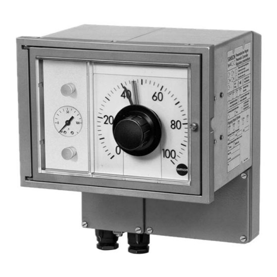
Series 430
Pneumatic Indicating Controllers
Type 3430
Type 3432 Controller Station
– with Type 3435 Transmitter Module for Pressure
– with Type 3436 Transmitter Module for Temperature
– with Type 3438 Transmitter Module for Temperature (Pt 100)
– for standardized signals
Version shown with lockable door and integrated
Type 3436 Transmitter Module for Temperature
Fig. 1 · Controller stations
Type 3431 Controller Station
– for standardized signals
Mounting and
Operating Instructions
EB 7030 EN
Edition October 2010
Advertisement
Table of Contents

Related Manuals for Samson 3430


Summary of Contents for Samson 3430
- Page 1 Series 430 Pneumatic Indicating Controllers Type 3430 Type 3432 Controller Station Type 3431 Controller Station – with Type 3435 Transmitter Module for Pressure – for standardized signals – with Type 3436 Transmitter Module for Temperature – with Type 3438 Transmitter Module for Temperature (Pt 100) –...
-
Page 2: Table Of Contents
Contents Contents Page Application ....... 4 Operation ....... 4 Settings at the controller modules . - Page 3 Contents Maintenance ......27 Checking the air supply ......27 Conversion .
-
Page 4: Application
Application Application Operation The Series 430 Pneumatic Indicating Con- Settings at the controller trollers are used for applications in process modules automation and industrial plants. The controllers directly measure the con- The controller module in the station can be trolled variables (pressure, temperature, accessed after the lock (Fig. -
Page 5: Air Supply
Operation Setting or modifying the operating direction: 2.1.2 Air supply Unfasten the screw in turnboard A (Fig. 2) (only with Type 3433 Controller Module) and lift it off together with the turnboard. If The position of the turnboard B (Fig. 2) with necessary, lever the board at the side. -
Page 6: Proportional-Action Coefficient Kp
Operation Unfasten screws (3.3) and pull off the 2.1.5 Rate time Tv connecting plate (3.2) together with nuts and bolts from the controller module. For Type 3433 Controller versions with de- Unscrew the hexagonal socket-head rivative-action component, the rate time Tv screws (3.4) at the side and lift the com- needs to be set at the restriction (11). -
Page 7: Setting The Limit Switches
Operation Setting the limit switches Only applies to controller stations with the limit switch option: To set the limit switches, first release the lock (4, Fig. 2) and open out the indicating unit (5). The contacts can be accessed at the back. -
Page 8: Commissioning
Commissioning Commissioning Prior to commissioning the control loop, check all devices to make sure they are con- nected correctly, do not leak and function properly. Release lock (4) and open out the indicating unit (5) to enable easy access to the operat- ing controls at the controller. -
Page 9: Setting The Operating Point In P And Pd Controllers
Commissioning actual value pointer to the green set Multiply both values with the values in point pointer. Close the T restriction the table (Fig. 5) and set as the favor- again. able settings for K , and T at the 6. -
Page 10: Smooth Automatic/Manual Mode Changeover
Commissioning adjuster (1.4). Note! The switch (1.6) can only be set to automatic The T restriction must be completely opened after the differential pressure indicator (1.8) with a P/PI controller is switched over to P is at zero. action to allow the operating point adjuster Set the set point again to the required value. -
Page 11: Construction
Construction is likewise required when used as a follower Construction controller. Additionally, inductive limit The controllers designed according to the switches, that are adjustable at a scale, can modular principle form an entire automation be mounted on the indicating units 1 or 2. unit consisting of a controller station, a con- Note! Refer to the corresponding Data troller module tuned to the local conditions,... -
Page 12: Controller Station
Principle of operation system (2.1). The deflection is converted by bellows measuring system of the controlled the pneumatic servo system (2.2) into a variable display and the controller module pneumatic signal (controlled variable x) as a pneumatic controlled variable signal which is proportional to the pressure p. - Page 13 Principle of operation 1.41 1.4 1.3 1.41 1.4 1.3 P PI P PI 2.9 2.8 Type 3432 with Type 3435 Transmitter for Pressure Type 3432 with Type 3436 Transmitter for Temperature 1.2 1.4 1.3 1.41 1.4 1.3 P PI P PI Type 3431 and 3432 for pneumatic standardized signals Type 3432 with manual/automatic switch (1.6), supply pressure regulator (1.9) and i/p converter...
-
Page 14: Controller Modules
Principle of operation sure y reaches the value related to the con- Controller modules trolled variable x and the proportional-ac- The controller modules are designed as tion coefficient K set at the screw. plug-in units. They are inserted into the Outside of the controller module, y is con- self-sealing hose fittings of the controller sta-... - Page 15 Principle of operation Type 3433-2 PI Controller Module The following versions of the controller mod- ules are similar in most aspects to the Type 3433-2 PI Controller Module, how- ever, they are fitted with, for example, an operating point adjuster, derivative element, or a selector switch, depending on the application.
- Page 16 Principle of operation Type 3433-4 PD Controller Module corresponds to Type 3433-1. Additionally, it contains a derivative element which produces the rate action with approx- imately ten times the gain in the input branch of the controlled variable x. The rate time can be adjusted at the T restriction.
-
Page 17: Type 3434 Controller Modules
Principle of operation The effect caused by the pressures in the di- 5.3.2 Type 3434 Controller aphragm chambers R1 and R2 is balanced. Modules The position of the force switch continues to change until the controller output pressure The controller modules have a round com- reaches a value which is related to the con- parator which operates according to the trolled variable x and the adjusted propor-... -
Page 18: Additional Modules
Principle of operation Additional modules 5.4.1 Type 6112 i/p Converter External reference variable w and/or con- trolled variable x can be issued as a current signal of 4(0) to 20 mA or 1 to 5 mA and converted by the i/p converter into a pneu- matic standardized signal of 0.2 to 1 bar. -
Page 19: Inductive Limit Switches
Principle of operation 5.4.4 Inductive limit switches The inductive limit switches indicate when the controlled variable x exceeds and/or falls below an adjustable limit value. Two metal tags are mounted to the pointer shaft of the controlled variable x which acti- vate associated proximity switches. -
Page 20: Installation
Installation Installation Pipe mounting Mounting to vertical or horizontal 2" pipes using a mounting part with bracket. Mounting Required mounting kit: Order no. 1400-6302. The controller station is designed for mount- ing onto pipes, walls or in panels. Protective roof (accessories): Refer to Figs. - Page 21 Installation Type 3432: Wall mounting Mounting using three straps Panel cut-out 188 x 255 Required mounting kit: Order no.1400-6301 Required panel mounting kit: Order no. 1400-6300. Panel mounting Mounting using four mounting elements Type 3431: (DIN 43835). Panel cut-out 188 x 138 Distance between centers to door approx.
-
Page 22: Changing Scales
Installation 6.1.1 Changing scales Installing the temperature sensor After unlocking the door (4, Fig. 4), the scale can be removed from the back of the Only applies to controller stations with display and, if necessary, replaced with a Type 3436 Transmitter Module special scale. - Page 23 Installation Mounting parts for bulb sensor Ø 12 mm, length Ø50 425 mm Clamping flange For wall mounting, e.g. pressureless containers or ducts Order no. 1090-9547 Mount flange to wall using two screws and attach temperature sensor with two other screws in the flange.
-
Page 24: Connections
Connections Connections 7.1.1 Typical applications Pneumatic connections The air connections underneath the device are designed as bores with ISO 228/1- Controller for standardized signals G 1/8 thread. The customary fittings for pipes or plastic hoses can be used. MU – Transmitter STR –... -
Page 25: Adjusting The Supply Air For Version With Supply Pressure Regulator
Connections 7.1.2 Adjusting the supply air for version with supply pressure regulator Only applies to Type 3432 Controller Sta- tions with supply pressure regulator (1.9). Hose connections for supply air are located directly above the corners of the supply pressure regulators on the bridge of the connecting plate (inside housing). -
Page 26: Electrical Connection
Connections Electrical connection Note on the selection of cables and wires: To install intrinsically safe circuits, observe The electrical components only apply to section 12 of the standard EN 60079-14: controller stations with i/p converter addi- 2003 (VDE 0165 Part 1). tional modules for controlled variable x, ex- To run multi-core cables or lines with more ternal reference variable wext and/or with... -
Page 27: Maintenance
Maintenance Type 3438 – – 4...20 mA + – 11 12 13 Supply Output External Setpoint 24V– – EEx i Sensor connection: No line compensation is required with four-wire connection. ϑ The resistance of the wires must be identical and the permissible line resistance of 50 W per wire is not to be + –... -
Page 28: Conversion
Conversion Undo bolts (3.3) and pull connecting Conversion plate (3.2) together with bolts and hex nuts off the controller module. Changing the controller Detach and mount the corresponding function cover plates and adjusters by unfasten- ing the M3 hexagon socket head screws The controller function can be changed ei- inside the housing. - Page 29 Conversion amplifier (14). Unscrew cover plate (11.1) (15) in place of the adjuster for operating and mount T restriction (11). point (12). P into PID: Modify as described for P into Note! PD. Additionally, replace adjuster (12) with We recommend replacing old O-rings as restriction (10).
-
Page 30: Exchanging The Transmitter Module
Conversion Exchanging the transmitter module The Type 3435 and Type 3436 Transmitter Module are fastened to the Type 3432 Con- troller Station over six screws. The supply air x is connected over two sili- cone hoses. The transmitter module can be replaced when a measuring element is defective or the measuring range is to be changed. -
Page 31: Use In Hazardous Areas
Use in hazardous areas Use in hazardous areas Caution! Observe the following for installations in po- The Type 3430 Controller Station is suitable tentially explosive atmospheres: On install- for use in potentially explosive atmospheres ing and performing service work on the de-... -
Page 32: Technical Data
Technical data Technical data Type 3432 and Type 3431 Controller Station Actual value display Measuring range 0.2 to 1.0 bar (3 to 15 psi) · Accuracy class 1.6 · Scale length 212 mm Set point adjustment Output 0.2 to 1.0 bar (3 to 15 psi) · Scale length 212 mm · Accuracy class 1.6 Adjuster for Output 0.2 to 1.0 bar (3 to 15 psi) ·... -
Page 33: Certificates
Technical data Type 3436 Transmitter Module for Temperature Measuring span °C –40 to +200 or –40 to +300 Measuring limit °C 150 to 300 Standard ranges °C –20 to +30 0 to 100 50 to 100 0 to 200 Overload limit 350 °C Perm. - Page 34 Technical data Electric Temperature Transmitter TTH200-E1H Fault indication Sensor breakage > 22 mA Sensor short-circuit < 3.6 mA Sensor wire breaking < 3.6 mA or > 22 mA Supply voltage with reverse 0 mA poles £ 0.1% or £ 0.2 K (whichever value is greater) Deviation from terminal-based linearity £...
- Page 35 EB 7030 EN...
- Page 36 EB 7030 EN...
- Page 37 EB 7030 EN...
- Page 38 EB 7030 EN...
- Page 39 EB 7030 EN...
- Page 40 EB 7030 EN...
- Page 41 EB 7030 EN...
- Page 42 EB 7030 EN...
- Page 43 EB 7030 EN...
- Page 44 EB 7030 EN...
- Page 45 EB 7030 EN...
- Page 46 EB 7030 EN...
- Page 47 EB 7030 EN...
- Page 48 EB 7030 EN...
- Page 49 EB 7030 EN...
- Page 50 EB 7030 EN...
- Page 51 EB 7030 EN...
- Page 52 SAMSON AG · MESS- UND REGELTECHNIK Weismüllerstraße 3 · 60314 Frankfurt am Main · Germany Phone: +49 69 4009-0 · Fax: +49 69 4009-1507 EB 7030 EN Internet: http://www.samson.de...
Need help?
Do you have a question about the 3430 and is the answer not in the manual?
Questions and answers