Table of Contents
Advertisement
Quick Links
SIMATIC
CP 541
Communications Processor
Manual
EWA 4NEB 812 6188-02
Edition 1
Preface, Contents
User Information
Overview
Communication Modes
Installing and Connecting the
CP 541
Assigning Parameters to the
CP 541
CP 541 with S5-95F/S5-115F
Diagnostics and Error Handling
Appendices
Technical Data
Optimizing SINEC L2
Parameters of DB1
DP Parameter Assignment
Message
DP Configuring Message
Definitions for the DP Master
Service Access Point (SAP) and
PROFIBUS Services
Program Examples
Glossary, Index
1
2
3
4
5
6
A
B
C
D
E
F
G
H
Advertisement
Table of Contents

Related Manuals for Siemens SIMATIC CP 541


Summary of Contents for Siemens SIMATIC CP 541
- Page 1 Preface, Contents User Information Overview SIMATIC Communication Modes Installing and Connecting the CP 541 CP 541 Communications Processor Assigning Parameters to the CP 541 Manual CP 541 with S5-95F/S5-115F Diagnostics and Error Handling Appendices Technical Data Optimizing SINEC L2 Parameters of DB1 DP Parameter Assignment Message DP Configuring Message...
-
Page 2: Edition
This device and its components may only be used for the applications described in the catalog or the technical description, and only in connection with devices or components from other manufacturers which have been approved or recommended by Siemens. This product can only function correctly and safely if it is transported, stored, set up, and installed correctly, and operated and maintained as recommended. - Page 3 Preface Purpose The information in this Manual allows you to connect a programmable controller of the SIMATIC S5 family to the CP 541; to connect a programmable controller of the SIMATIC S5 family via the CP 541 to SINEC L2; to integrate a programmable controller of the SIMATIC S5 family via the CP 541 as a DP slave in SINEC L2-DP;...
- Page 4 Preface Other Pertinent This CP 541 Manual describes the SINEC L2 interfacing of the CP 541. Manuals The assigning of parameters to the programmable controller connected to the CP 541 as a SINEC L1 slave can be found in the relevant manual. The description of SINEC L2-DP and a DP master, such as the IM 308-C master interface module, are not part of this Manual.
-
Page 5: Table Of Contents
Contents Overview ............. . . Performance Features of the CP 541 . - Page 6 Contents 5.3.4 Setting the Safety Times ......... . 5-16 5.3.5 Example for Calculating the Local Cycle Times...
- Page 7 Contents Glossary Index Figures CP 541 in the SIMATIC Environment ....... View of the CP 541 .
- Page 8 Contents Tables LED Indicators of the CP 541 ........Mode Switch of the CP 541 .
-
Page 9: Overview
Overview Introduction The CP 541 provides a link between programmable controllers of the SIMATIC S5 family via SINEC L2 and other programmable controllers. Given in this chapter is a summary covering the application of the CP 541 and its characteristics. Definitions The following situation is covered by this Manual: The programmable controller connected to the PG/PLC port is referred to... -
Page 10: Performance Features Of The Cp
Overview Performance Features of the CP 541 Introduction The significant performance features of the CP 541 are described in the fol- lowing. Fields of You can use the CP 541 for the following fields of application: Application Subsequent networking of installed programmable controllers of the SI- MATIC S5 family Substitute for SINEC L1 For connecting failsafe programmable controllers of the SIMATIC S5... -
Page 11: Communication Modes
Overview Advantages for the The CP 541 offers you various advantages. User It allows parallel operation of the various communication modes. It supports the safety-related connection of failsafe programmable con- trollers of the SIMATIC S5 family via SINEC L2. It can be used with most SIMATIC S5 systems. It allows simple retrofitting on existing systems. -
Page 12: The Cp 541 In The Simatic Environment
Overview The CP 541 in the SIMATIC Environment Incorporation in Figure 1-1 shows the incorporation of the CP 541 in the SIMATIC environ- SIMATIC ment. On account of the various communication modes, possible combinations of communication modes and number of connectable programmable controllers, Figure 1-1 is merely an example. -
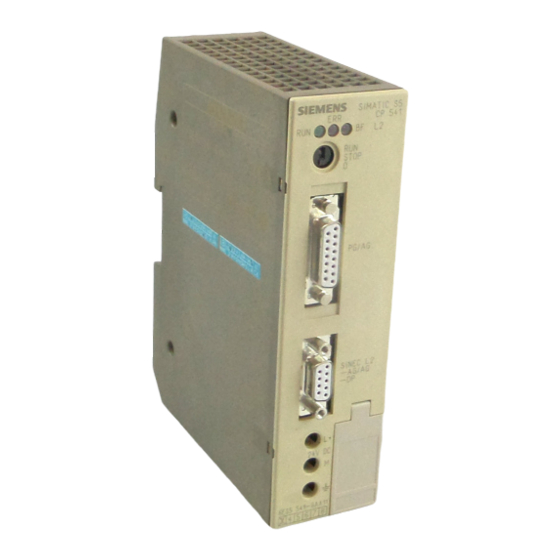
Page 13: View Of The Cp 541
Overview View of the CP 541 View Figure 1-2 is a view of the CP 541 SIMATIC S5 CP 541 LED indicator BF L2 Mode switch STOP PG/AG Connector for PG/PLC SINEC L2 – AG/AG Connector for SINEC L2 – DP Terminals for 24 V DC 24 V DC... -
Page 14: Led Indicators Of The Cp 541
Overview LED Indicators The CP 541 has three LEDs to indicate the operational state of the CP 541 and any errors. Table 1-1 LED Indicators of the CP 541 Color Position Meaning Green Left Operational state Middle Error in CP 541 or at PG/PLC connection BF L2 Right Error at L2 connection or SINEC L2 not... -
Page 15: Suitable Programmable Controllers For The Cp 541
Overview Suitable Programmable Controllers for the CP 541 Introduction The summaries in Tables 1-4 and 1-5 indicate the programmable controllers of the SIMATIC S5 family which you can connect to the CP 541. Also given are the communication modes you can install by means of CP 541 via SINEC L2 and the appropriate programmable controllers. - Page 16 Overview One Station via When one SINEC L2 station is connected via CP 541, Table 1-5 shows the CP 541 possible communication modes in relation to the appropriate programmable controllers of the SIMATIC S5 family. Table 1-5 Connectable Programmable Controllers and Communication Modes; one Station Connected to SINEC L2 via CP 541 IM 308B CP 5430...
-
Page 17: Communication Modes
Communication Modes Introduction This chapter provides an overview of the communication modes you can use via the CP 541. Declarations The following two declarations apply to the entire Manual. You require these declarations to facilitate understanding of the various communication modes. Node address The node address is the address with which the programmable controller connected to the CP 541 is accessed by it. -
Page 18: Plc-Plc Connection
Communication Modes PLC-PLC Connection Introduction The PLC-PLC connection serves for message-oriented communication be- tween two programmable controllers, without a detour via an additional sta- tion. Message Length Each message of the non-safety-related PLC-PLC connection can contain up to 64 bytes of data. Parameter If you install a PLC-PLC connection, you must parameterize the CP 541 as Assignment... -
Page 19: Dp Connection
Communication Modes DP Connection Introduction The DP connection is data-oriented non-safety-related communication be- tween a DP master and a DP slave. Message Length The DP connection can contain up to 16 words of data in each direction. Parameter You install the DP connection in the connected programmable controller as a Assignment connection with node address 0 (see Section 4.3). -
Page 20: Broadcast Via Fdl Connection
If only the CP 541 and another station in SINEC L2 use this SAP, you can utilize this special form of broadcast to establish a connection to any other non-Siemens device. Communications Processor CP 541 EWA 4NEB 812 6188-02... -
Page 21: Installing And Connecting The Cp 541
Installing and Connecting the CP 541 Introduction When you have studied this chapter, you will be able to install, connect and start up the CP 541. Installation of Programmable controllers of the SIMATIC S5-90U, S5-95U/F and S5-100U Equipment series must be installed in electrical apparatus rooms or in enclosed housings, such as metal or plastic cabinets. -
Page 22: Installing The Cp 541
Installing and Connecting the CP 541 Installing the CP 541 Introduction The CP 541 is mounted like a programmable controller of the SIMATIC S5 family, for example the S5-95U or S5-100U, on a standard rail to EN 50022-35 15. Mounting Mount the CP 541 on a standard rail. -
Page 23: Connecting The Cp 541
Installing and Connecting the CP 541 Connecting the CP 541 Introduction Connect the CP 541 as follows. Supply of Power We recommend the use of a SITOP power supply unit. If you do not use a SITOP power supply unit, you must use a safety-separated power supply meeting the requirements given in Appendix A. -
Page 24: Isolation Of Terminals
Installing and Connecting the CP 541 Connecting the Connect the bus cable to the bus connector, as explained in the instructions Bus Cable with the bus connector. Electrical Separa- The PG/PLC interface and the SINEC L2 interface are safety-separated (iso- tion (Isolation) lated) via optocouplers. -
Page 25: Starting Up The Cp 541
Installing and Connecting the CP 541 Starting up the CP 541 Startup Proceed in the following order for the first startup. Step Action Meaning Mount the CP 541 on the rail. See Section 3.1. Make connections for a programmer, the See Section 3.2 SINEC L2 and the power supply. -
Page 26: Operating States Of The Cp 541
Installing and Connecting the CP 541 Operating States of the CP 541 Introduction You can subdivide the operational behavior of the CP 541 into individual operating states and their transitions, as explained in following. Operating States We subdivide the operational behavior into the following operating states and state transitions: POWER ON POWER ON is understood to mean the behavior when the CP 541 has... -
Page 27: Power On
Installing and Connecting the CP 541 3.4.1 POWER ON Power On In POWER ON, the CP 541 reacts as shown in the following flowchart. Step Flowchart Explanation Whether or not you set the mode switch from 0 to STOP, or whether Power Switch on restored... -
Page 28: Stop State
Installing and Connecting the CP 541 3.4.2 STOP State Meaning In the STOP state, the CP 541 is initialized and the interface for the con- nected programmable controller is not activated. RUN LED In the STOP state, the RUN LED flashes at 2 Hz. Programmer In the STOP state, you can connect a programmer to the CP 541. -
Page 29: Start
Installing and Connecting the CP 541 3.4.3 START START The START is explained in the following flowchart. Step Flowchart Explanation The CP 541 is in the STOP state. STOP state RUN LED flashes at 2 Hz. Setting The CP 541 evaluates the set- of mode ting of the mode switch. -
Page 30: Run State
Installing and Connecting the CP 541 3.4.4 RUN State Meaning In the RUN state, both the PLC interface and the SINEC L2 interface are ready to exchange data. Operator inputs via the programmer are not possible in the RUN state. Exchange of Data The CP 541 transfers the data from the connected programmable controller to SINEC L2 and vice versa. -
Page 31: Assigning Parameters To The Cp 541 For The Connections
Assigning Parameters to the CP 541 for the Connections Introduction This chapter contains instructions for assigning parameters to the CP 541 with minimum complexity, for the individual connections between the con- nected programmable controller and SINEC L2. We will explain which parameters you must change in DB1 in the reset state. A reset is only possible from the programmer. -
Page 32: Configuring A Plc-Plc Connection
Assigning Parameters to the CP 541 for the Connections Configuring a PLC-PLC Connection Introduction The PLC-PLC connection is comparable to a point-to-point link between two programmable controllers. You can easily install the PLC-PLC connection with the parameters stored in the default DB1. Assigning Parame- You assign parameters for the PLC-PLC connection via the CP 541 as shown ters to CP 541... -
Page 33: Configuring The Broadcast Mode
Assigning Parameters to the CP 541 for the Connections Configuring the Broadcast Mode Introduction You can easily establish the broadcast mode with the parameters stored in the default DB1. Assigning Parame- You assign parameters for the broadcast mode via the CP 541 as shown in the ters to CP 541 following table. -
Page 34: Configuring A Dp Connection
Assigning Parameters to the CP 541 for the Connections Configuring a DP Connection Introduction You have a choice of two configurations for the DP connection. You can op- tionally operate the CP 541 purely as a DP slave or in mixed mode with a PLC-PLC connection and broadcast. - Page 35 Assigning Parameters to the CP 541 for the Connections In the In the connected programmable controller, you must observe the following Programmable points when assigning parameters: Controller The station number set in the CP 541 must be identical to the node ad- dress of the connected programmable controller.
- Page 36 Assigning Parameters to the CP 541 for the Connections Communications Processor CP 541 EWA 4NEB 812 6188-02...
-
Page 37: Cp 541 With S5-95F/S5-115F
S5-95F and S5-115F. If you do not use either of these two programmable controllers, you can skip this chapter. Supported Failsafe The CP 541 supports safety-related data transmission with the following PLCs Siemens failsafe programmable controllers: Table 5-1 Supported Failsafe Programmable Controllers Order No. From Revision Level... -
Page 38: Communication Modes
CP 541 with S5-95F/S5-1 15F Communication Modes Introduction Section 5.1 provides a summary of the safety-related communication modes you can use via the CP 541. Safety-Related Safety-related communication is possible via: Communication PLC-PLC connection Broadcast via FDL Other Communica- Other communication modes are possible apart from the safety-related com- tion Modes munication modes. -
Page 39: Safety-Related Plc-Plc Connection
CP 541 with S5-95F/S5-1 15F 5.1.1 Safety-Related PLC-PLC Connection Introduction The safety-related PLC-PLC connection serves for message-oriented commu- nication between two failsafe programmable controllers, without a detour via an additional station. Message Length Each message of the safety-related PLC-PLC connection can contain up to 60 bytes of net data, plus 4 bytes for data detection and correction. -
Page 40: Safety-Related Broadcast Via Fdl
CP 541 with S5-95F/S5-1 15F 5.1.2 Safety-Related Broadcast via FDL Introduction With the safety-related broadcast, you transwith messages to all failsafe L2 stations listening on the SINEC L2 via FDL and the set SAP, and using ser- vice SDN. Message Length Each safety-related broadcast message can contain up to 60 bytes of net data plus 4 bytes for data detection and correction. -
Page 41: Configuring Connections
CP 541 with S5-95F/S5-1 15F Configuring Connections Introduction This chapter contains instructions on assigning parameters to the CP 541 for operation with S5-95F or S5-115F. DP Connection Instructions on installing a DP connection can be found in Section 4.3. The DP connection is always non-safety-related. -
Page 42: Configuring A Safety-Related Plc-Plc Connection
CP 541 with S5-95F/S5-1 15F 5.2.1 Configuring a Safety-Related PLC-PLC Connection Introduction The safety-related PLC-PLC connection is comparable to a point-to-point connection between two failsafe programmable controllers. You can easily install the safety-related PLC-PLC connection with the pa- rameters stored in the default DB1. Assigning Parame- You assign parameters for the safety-related PLC-PLC connection via the CP ters to the CP 541... -
Page 43: Configuring A Non-Safety-Related Plc-Plc Connection
CP 541 with S5-95F/S5-1 15F 5.2.2 Configuring a Non-Safety-Related PLC-PLC Connection Introduction You need this chapter to set up a non-safety-related PLC-PLC connection from an S5-115F. You install the non-safety-related PLC-PLC connection with the S5-95F as shown in Section 4.1. Assigning Parame- You assign parameters for the non-safety-related PLC-PLC connection via ters to the CP 541... -
Page 44: Configuring The Safety-Related Broadcast Mode
CP 541 with S5-95F/S5-1 15F 5.2.3 Configuring the Safety-Related Broadcast Mode Introduction You can easily install the safety-related broadcast mode with the parameters stored in the default DB1. Assigning Parame- You assign parameters for the safety-related broadcast mode via the CP 541 ters to the CP 541 as shown in the following table. -
Page 45: Safety Times
CP 541 with S5-95F/S5-1 15F Safety Times Introduction When using the safety-related PLC-PLC connection or the safety-related broadcast, you must observe the process-dependent safety times. You must agree the safety times with the inspector. Fundamental Rule When using the CP 541 with S5-95F or S5-115F, you must comply with all the safety conditions specified in the manual for the programmable control- ler. -
Page 46: Local Cycle Time For Cp 541
CP 541 with S5-95F/S5-1 15F 5.3.1 Local Cycle Time for CP 541 Introduction Based on the cycle time in SINEC L1, we use the local cycle time for opera- tion of the CP 541. You need the local cycle time to verify the receive safety time. Definition The local cycle time is the time elapsing until all the maximum possible mes- sages between the CP 541 and the connected programmable controller have... -
Page 47: Calculating The Local Cycle Time
CP 541 with S5-95F/S5-1 15F 5.3.2 Calculating the Local Cycle Time Introduction The following is an explanation for calculating the local receive and send cycle times for a connection between a CP 541 and a connected program- mable controller. Preconditions The following preconditions apply to the calculation: The send delay time (POL) must not be longer than the transit time of the shortest send message, plus the transit time of the shortest receive mes-... - Page 48 CP 541 with S5-95F/S5-1 15F Preparing the Before being able to calculate the cycle times for receiving and sending, you Calculation must carry out the following actions: Step Action Meaning Sort the messages according to message To calculate the local cycle time, you need direction.
- Page 49 CP 541 with S5-95F/S5-1 15F Local Cycle Time Calculate the local cycle time for sending as follows: for Sending Step Action Draw up a simple table with two rows and the number of columns corresponding to the send messages. Mark the first row “Send” and the second row “Receive”. Enter in the “Send”...
-
Page 50: Condition For The Sinec L1 Safety Time For Receiving
CP 541 with S5-95F/S5-1 15F 5.3.3 Condition for the SINEC L1 Safety Time for Receiving Introduction When planning a safety-related system, you and the inspector agree a pro- cess-dependent SINEC L1 safety time for receiving. Different Formula When using the CP 541, you must verify the condition for the SINEC L1 safety time for receiving, according to a formula. - Page 51 CP 541 with S5-95F/S5-1 15F Verifying the Use the following table to verify the receive safety time: Receive Safety Time Step Action Meaning Calculate the local cycle times See Section 5.3.2 for sending and receiving. Verify the condition for the If the condition is fulfilled, you SINEC L1 safety time for re- can use the CP 541 for commu-...
-
Page 52: Setting The Safety Times
CP 541 with S5-95F/S5-1 15F 5.3.4 Setting the Safety Times Introduction Explained in the following are the actions for setting the safety times in the failsafe programmable controller. Safety Time for Proceed as follows to determine the SINEC L1 safety time for receiving for Receiving in the an S5-95F. - Page 53 CP 541 with S5-95F/S5-1 15F Safety Time in the Proceed as follows to determine the SINEC L1 safety time for an S5-115F. S5-115F Step Action Meaning Verify the conditions for the SINEC L1 The calculated value must be less than the safety time for receiving, using the formula SINEC L1 safety time for receiving.
-
Page 54: Configuration Example For Calculating The Local Cycle Times
CP 541 with S5-95F/S5-1 15F 5.3.5 Example for Calculating the Local Cycle Times Introduction An example for calculating the local cycle times is given here for clarifica- tion. Configuration There are three programmable controllers, each with a CP 541 and intercon- Example nected via SINEC L2. - Page 55 CP 541 with S5-95F/S5-1 15F Node 1 Calculation of the local cycle times: Two receive messages and two send messages are present. The message transit times are given by: – Sending of 20+4 bytes to Station 2: 24 2 ms + 44 ms = 92 ms –...
- Page 56 CP 541 with S5-95F/S5-1 15F Node 2 Calculation of local cycle times: Two receive messages and one send message are present. The message transit times are given by: – Sending of 10+4 bytes to Station 1: 14 2 ms + 44 ms = 72 ms –...
- Page 57 CP 541 with S5-95F/S5-1 15F Node 3 Calculation of local cycle times: Two receive messages and one send message are present. The message transit times are given by: – Sending of 8 bytes to Station 1: 8 2 ms + 44 ms = 60 ms –...
-
Page 58: Example Of Verification Of Safety Times
CP 541 with S5-95F/S5-1 15F 5.3.6 Example of Verification of Safety Times Example The example previously described (see Section 5.3.5) serves for verifying the safety times. We will now determine the safety time for a connection between the two pro- grammable controllers, Stations 1 and 2. - Page 59 CP 541 with S5-95F/S5-1 15F Result With the data in this example, a safety-related connection can be established between the two programmable controllers via SINEC L2, using the CP 541, because both the safety time of Station 1 and safety time for receiving of Sta- tion 2 are less than the specified value.
-
Page 60: Redundant Sinec L2 Configuration
CP 541 with S5-95F/S5-1 15F Redundant SINEC L2 Configuration Introduction You can configure SINEC L2 with redundancy for a safety-related connec- tion between two or more failsafe programmable controllers. Redundant op- eration is not subject to any restrictions. Configuration Shown in Figure 5-5 is the configuration for SINEC L2 in a redundant con- figuration for communication using two failsafe programmable controllers. -
Page 61: Diagnostics And Error Handling
Diagnostics and Error Handling Introduction Diagnostics offers you the facility for monitoring the proper functioning of the CP 541 and evaluating any errors. Information on incorrect operational states are stored by the CP 541 in diag- nostics block DB2. If necessary, the CP 541 generates the DP diagnostics. Diagnostic The CP 541 issues a diagnosis at different locations: Facilities... -
Page 62: Local Diagnostics With Leds
Diagnostics and Error Handling Local Diagnostics with LEDs Indication The CP 541 has three LEDs to indicate the current operational state and any errors. Operational State The current operational state of the CP 541 is indicated with three LEDs. RUN LED The current state is indicated with the green RUN LED. - Page 63 Diagnostics and Error Handling Evaluating the Proceed as follows to evaluate the diagnosis and clear any error: Diagnosis Step Action Explanation Set the mode switch to STOP. DB2 can only be read out with the switch set to STOP. Connect the programmer to the CP 541. You cannot access DB2 via a programmable controller.
-
Page 64: Diagnostics Block
Diagnostics and Error Handling Diagnostics Block Introduction The CP 541 stores in the diagnostics block (DB2) all data on events occur- ring during the start and in operation. Reading out DB2 You can read out the diagnostics block in the STOP mode with a PG. You connect the PG to the PG/PLC connector. -
Page 65: Structure Of The Diagnostics Block
Diagnostics and Error Handling 6.2.1 Structure of the Diagnostics Block Introduction The following is a summary of the structure of the diagnostics block (DB2). This is where the CP 541 stores information on all detected error states. Detailed information on DB2 can be found in the following sections. Structure The diagnostics block contains the ranges given in Table 6-2. -
Page 66: Db1 Errors
Diagnostics and Error Handling 6.2.2 DB1 Errors Given in DW1, in the event of an error, is the number of the byte at which the error in DB1 has occurred. For some errors, the address of the errored block is indicated. Display on the For the display of a DB on the PG, the data are not numbered in bytes but in Programmer... -
Page 67: Db1 Error Codes
Diagnostics and Error Handling Table 6-4 DB1 Error Codes, continued Error Code Meaning Meaning Remedy Remedy In DL In DR Parameter syntax error Verify the structure of parameters in the speci- fied block and fully specify all parameters. Argument syntax error or over- Observe the structure of individual parameters range/underrange and enter the right value. - Page 68 Diagnostics and Error Handling Table 6-4 DB1 Error Codes, continued Error Code Meaning Meaning Remedy Remedy In DL In DR The transmission rate (BDR) Lowest permissible transmission rate is 93.75 chosen is too low. Kbps. Enter the right value. The own station number is en- Delete the own station number (value of TLN) tered in PRI.
-
Page 69: Sinec L2 Bus Errors
... B1 An internal fatal error has occurred. Replace the module..FF Consult your Siemens office with the error code. Clearing Errors If the BF L2 LED lights up during operation, the CP 541 requires a POWER OFF/POWER ON transition to restart. -
Page 70: Sinec L1 Message Errors
Diagnostics and Error Handling 6.2.4 SINEC L1 Message Errors Error Codes The error codes for SINEC L1 message errors are stored in bytes in the diag- nostics block (DB2) or the CP 541, in DW13 to DW17. Meanings of the error codes and the remedies are given in Table 6-6. Table 6-6 SINEC L1 Message Errors Error Code... - Page 71 Diagnostics and Error Handling Table 6-6 SINEC L1 Message Errors, continued Error Code Meaning Remedy Connected PLC does not have the Specify the same TLN (node address/sta- same TLN as CP 541. tion number) in both devices. The CP 541 remains at RUN. The CP 541 is at RUN and a pro- If you connect the programmer to the CP grammer is connected.
-
Page 72: Internal Errors
Make a note of the error code. The error code is stored from DL27 onward. Replace the CP 541. Follow the instructions in Chap- ter 3. Consult your Siemens office – with the error message. Communications Processor CP 541 6-12 EWA 4NEB 812 6188-02... -
Page 73: Dp Diagnostic Message Using The Example Of An Im 308-C With Fb Im308C
Diagnostics and Error Handling DP Diagnostic Message Using the Example of an IM 308-C with FB IM308C Introduction The DB diagnostic message is structured to Standard DIN E 19245, Part 3, and provides information on the DP slave or CP 541. Choice of Two diagnostic facilities are available: Diagnosis... -
Page 74: Communications Processor Cp
Diagnostics and Error Handling Output of the The CP 541 indicates to the DP master that there is a diagnosis. If a new er- Diagnosis ror occurs, the diagnosis is automatically fetched by the DP master. This pro- cedure is repeated with each change of diagnosis. Summary of this Section Contents... -
Page 75: Structure Of The Diagnosis
Diagnostics and Error Handling 6.3.1 Structure of the Diagnosis Size The diagnostic message contains 8 bytes of data. Structure The structure of the diagnostic message complies with the specifications of the PROFIBUS DP standard. The structure of the entire diagnosis is repre- sented in Table 6-7. -
Page 76: Structure Of Station Status 1 (Byte 0)
Diagnostics and Error Handling 6.3.2 Contents of the DP Standard Section DP Standard The first 6 bytes of the diagnostic message (byte 0 to byte 5) are also known Section as the DP standard section. This information is exchanged between the CP 541 and the DP master. You do not normally require this information. - Page 77 Diagnostics and Error Handling Station Number of Byte 3 contains the station number of the DP master which assigned parame- DP Master ters to the DP slave. Only this DP master has read and write access to this DP slave. The station number is given the default FF during the start.
-
Page 78: Device-Related Diagnosis
Diagnostics and Error Handling 6.3.3 Device-Related Diagnosis Range The device-related diagnosis is contained in bytes 6 and 7. Contents Table 6-10 Structure of Bytes 6 and 7 of the Diagnostic Message Byte Value Content Length of device-related diagnosis in bytes inc. header Device-related diagnosis The significance of the individual bits can be found in Table 6-11. -
Page 79: Example Of Configuration
Diagnostics and Error Handling 6.3.4 Example of a Diagnostic Call with IM308-C and FB IM308C Example Given here is a short example of the S5-115U with IM 308-C as the DP mas- ter. It shows how you read the slave diagnosis for the CP 541 into your pro- grammable controller with FB IM308C. -
Page 80: Dp Diagnosis In The Programmable Controller
Diagnostics and Error Handling DP Diagnosis in the Programmable Controller Introduction The CP 541 informs the connected programmable controller of a failure of the DP connection to the DP master. This chapter describes how this is achieved and what you must take into ac- count. -
Page 81: Technical Data
European Norms (ENs) listed there. The EU conformity declarations are kept available for the appropriate autho- rities at the following address, in compliance with the above EU Guideline, Article 10: Siemens Aktiengesellschaft Bereich Automatisierungstechnik AUT E 148 Postfach 1963 D-92209 Amberg Field of SIMATIC products are designed for operation in industry. - Page 82 Technical Data Climatic environmental conditions Electromagnetic compatibility (EMC)/interference to IEC 1131-2 immunity Temperature Discharge of static electricity to IEC 801-2 Severity 3 Operation Discharge of static 8 kV discharge in air electricity Horizontal installation 0 ... + 60 C Discharge on all parts ac- cessible to the user in nor- Vertical installation 0 ...
- Page 83 Technical Data Dimensions and weight Interface data Dimensions Communication modes Height 162 mm PLC-PLC 29 connections Width 46 mm Broadcast 125 connections Depth 120 mm DP connection 1 to DP master Weight 415 g Message length for PLC-PLC 64 bytes max. Broadcast 64 bytes max.
-
Page 84: Cp 541 Dimension Drawing
Technical Data Dimension The dimension drawing for the CP 541 is given in Figure A-1. Drawing SIMATIC S5 CP 541 BF L2 STOP PG/PLC SINEC L2 - PLC/PLC - DP 24 VDC (0V) 6ES5 541-8AA11 1 2 3 4 5 6 Figure A-1 CP 541 Dimension Drawing Communications Processor CP 541 EWA 4NEB 812 6188-02... -
Page 85: Optimizing Sinec L2
Optimizing SINEC L2 Introduction By optimizing the parameters in DB1, you can speed up message processing in the CP 541 and, therefore, also SINEC L2. A full description of DB1 is given in Appendix C. Parameter BSAP You specify the SAP (service access point) for broadcast with parameter BSAP. - Page 86 Optimizing SINEC L2 Optimization You can optimize parameter HSA as follows: Specify the station numbers of all active stations in a connected series. Begin the addressing of active stations with station number 1. Assign the station number of the highest active station to HSA. Specify no reserve or only slight reserves for any active stations to be inserted later.
- Page 87 Optimizing SINEC L2 Example Here are two examples of a priority list. PRI 1, 6, 2 Stations 1, 6 and 2 will always be interrogated successively. Each station has the same priority. Messages from other stations will not be trans- mitted.
- Page 88 Optimizing SINEC L2 Parameter TRT You specify the token rotation time for SINEC L2 with parameter TRT. Given in Appendix C.7 is a detailed description for calculating parameter TRT and, therefore, optimizing it. Communications Processor CP 541 EWA 4NEB 812 6188-02...
-
Page 89: Parameters Of Db1
Parameters of DB1 Introduction You assign parameters to the CP 541 with DB1 in the CP 541. You thus de- termine the operational behavior of the CP 541. Modifying DB1 To be able to modify DB1 in CP 541, you must switch the CP 541 to STOP and connect a PG to the PG/PLC input. -
Page 90: Structure Of Db1
Parameters of DB1 Structure of DB1 Introduction With your entries in DB1, you coordinate the exchange of data between the connected programmable controller and SINEC L2. Structure DB1 is subdivided into three areas, as shown in Figure C-1. You can define the following three areas in DB1: General SINEC L2 parameters, block identifier SL2 (SINEC L2) CP 541-specific parameters, block identifier COM... -
Page 91: Syntax Of Db1
Parameters of DB1 Syntax of DB1 Introduction The structure of DB1 and the syntax of the individual parameters comply with fixed rules. Given in Figure C-2 is the syntax for DB1. DB1: Fill charac- Fill charac- ”DB1” Parameter block ”;” ”END”... -
Page 92: General Sinec L2 Parameters - Block Identifier Sl2
Parameters of DB1 General SINEC L2 Parameters - block Identifier SL2 Meaning With block identifier SL2, you enter the general parameters for the SINEC L2. An explanation of individual parameters can be found in Table C-1. Observe the syntax of DB1 (see Appendix C.2). Table C-1 SL2 Parameters Parameter... -
Page 93: Necessary Basic Parameters According To Station Status (Sta
Parameters of DB1 Table C-1 SL2 Parameters, continued Parameter Values Meaning 0 ... 494 Setup time The setup time is the time which may elapse between an event and the reaction to the event. The formula is: (SDT 2 35)/2 SET (SDT 1 35)/2. This parameter must be set identically in all stations. -
Page 94: Dp/Fms Bus Profile (In Bit Times
Parameters of DB1 Bus Profiles Various bus profiles are defined for SINEC L2. The CP 541 supports the fol- lowing profiles: DP/FMS PROFIBUS-DP DP with IM 308-B User defined DP/FMS Table C-3 DP/FMS Bus Profile (in Bit Times) Parameter Transmission rate in Kbps 93.75 187.5 1500... -
Page 95: User-Defined Bus Profile (In Bit Times
Parameters of DB1 User Defined Table C-6 User-Defined Bus Profile (in Bit Times) Parameter Transmission rate in Kbps 93.75 187.5 1500 SET (T ST (T 1000 3000 SDT 1 (min T SDT 2 (max T These values are entered in default DB1. Adjusting the You must use the basic parameters of the slowest station in SINEC L2. -
Page 96: Cp 541-Specific Parameters - Block Id Com
Parameters of DB1 CP 541-Specific Parameters - Block ID COM Meaning You enter the specific parameters for the CP 541 with block identifier COM. An explanation of the individual parameters can be found in Table C-7. Observe the syntax of DB1 (see Appendix C.2). Table C-7 COM Parameters Parameter... - Page 97 Parameters of DB1 Table C-7 COM Parameters, continued Parameter Values Meaning UPDL 0 ... 10 Update delay (receive delay time) With the receive delay time, you specify the time after which a new message can be sent from the CP 541 to the connected programmable controller. If you enter the value 0, there will be no delay and a message received from SINEC L2 will be im- mediately sent to the connected programmable controller.
-
Page 98: Dp Parameters - Block Id "Dps
Parameters of DB1 DP Parameters – Block ID ”DPS” Meaning You specify the parameters for the DP connection with block identifier DPS. An explanation of the individual parameters can be found in Table C-8. With block identifier DPS, you inform the CP 541 that it is to store data for node address 0 in the DP transfer area. - Page 99 Parameters of DB1 DP Connection If you configure a DP connection, at least one of the two parameters NWI or NWO must be 0. Special Note for If you have configured a DP connection in an S5-115F, you cannot addition- S5-115F ally install a non-safety-related PLC-PLC connection.
-
Page 100: Default Db1
Parameters of DB1 Default DB1 Introduction When delivered and after a reset, the CP 541 contains a default DB1. The settings of the default DB1 in the CP 541 are such that you can use it im- mediately in most cases. You need only adjust the station number. Default DB1 The following list contains an explanation of the default DB1. -
Page 101: Default Values In Db1
Parameters of DB1 Defaults All values are preset as defaults. If individual parameters are marked as re- marks, the values stored internally will be used by the CP 541. The default values are listed in Table C-9. Table C-9 Default Values in DB1 Parameter BSAP UPDL... -
Page 102: Calculating The Token Rotation Time
Parameters of DB1 Calculating the Token Rotation Time Meaning The token rotation time (TRT, target rotation time) specifies the time re- quired until all active stations have had possession of the token once. The calculation for the token rotation time is given in the following. Default The token rotation time has the default 30000 bit times in DB1 of the CP 541. -
Page 103: Basic Load On Sinec L2 (In Bit Times
Parameters of DB1 Basic Load The values for the basic load as a function of message type and transmission rate can be found in Table C-10. Table C-10 Basic Load on SINEC L2 (in Bit Times) Message type g yp Transmission rate in Kbps 93.75 187.5... -
Page 104: Example Of Calculation Of The Token Rotation Time
Parameters of DB1 Example of Calculation of the Token Rotation Time Example The following example is intended to clarify the calculation of the token rotation time. It is based on a transmission rate of 500 Kbps. Step Action Implementation Determine the number of stations in The following stations are present: SINEC L2. - Page 105 Parameters of DB1 Step Action Implementation Calculate the load caused by the data for You must add 11 bit times for each trans- each message. mitted data byte. Load: 150 11 1650 bit times Add up the individual loads. Basic load: 4265 bit times Data: 1650 bit times...
- Page 106 Parameters of DB1 Communications Processor CP 541 C-18 EWA 4NEB 812 6188-02...
-
Page 107: Dp Parameter Assignment Message
DP Parameter Assignment Message Introduction The CP 541 needs the parameter assignment message in the DP start; it is explained here. The DP master sends the DP parameter assignment message to the DP slave (CP 541). Structure The parameter assignment message contains 7 bytes of data, byte 0 to byte 6. It is structured according to DP Standard DIN E 19254, Part 3. -
Page 108: Structure Of The Station Status In The Parameter Assignment Message
DP Parameter Assignment Message Station Status The operational behavior of the CP 541 as a DP slave is defined with the sta- tion status. Its reactions to other L2 masters are defined, and whether the SYNC and FREEZE mode and the watchdog are used. The SYNC and FREEZE mode are not supported by the CP 541. -
Page 109: Dp Configuring Message
DP Configuring Message Introduction The CP 541 requires the configuring message in the start after the parameter assignment message, as described in the DP standard. The DP master sends the DP parameter assignment message to the DP slave (CP 541). Meaning The lengths of input and output data are specified in the configuring mes- sage. - Page 110 DP Configuring Communications Processor CP 541 EWA 4NEB 812 6188-02...
-
Page 111: Definitions For The Dp Master
Definitions for the DP Master Introduction For the DP connection between the CP 541 and the DP master, the protocol specified in Standard DIN E 19245, Part 3, is used. Definitions Given in the following list is a summary of definitions for the CP 541 which are established for the DP connection. - Page 112 Definitions for the DP Master DMD File All slave-related characteristics are stored in a device master data (DMD) file. The structure of the DMD file is defined in Standard DIN 19245, Part 3. If you need the DMD file, you can retrieve it via modem under telephone number 0911/737972.
-
Page 113: Service Access Point (Sap) And Profibus Services
Service Access Point (SAP) and PROFIBUS Services Introduction You do not necessarily require information on the service access points to work with the CP 541. You can specify a service access point for broadcast with parameter BSAP in frame COM of DB1. The PROFIBUS services used by the CP 541 are given in Table G-2. -
Page 114: Profibus Services
Service Access Point (SAP) and PROFIBUS Services PROFIBUS Messages from the connected programmable controller are converted by the Services CP 541 to the PROFIBUS services given in Table G-2. Table G-2 PROFIBUS Services Communication mode PROFIBUS service Priority PLC-PLC connection Low priority Broadcast Low priority... - Page 115 Program Examples Introduction In this chapter, we have assembled three examples to demonstrate the incor- poration of the CP 541 and the effects on the user program of the connected programmable controller. Summary of this Section Contents Page Section PLC-PLC Connection DP Connection Safety-Related PLC-PLC Connection: S5-95F - S5-115F H-12...
-
Page 116: Configuration For A Plc-Plc Connection
Program Examples PLC-PLC Connection Introduction This example shows a PLC-PLC connection between two S5-95Q program- mable controllers. It is a bidirectional PLC-PLC connection. Program Sequence From each programmable controller (station 11 and station 12), the value of IB 33 is sent with a positive-going edge at I 32.0 to the partner PLC and indi- cated there with QB 32. - Page 117 Program Examples DB1 in S5-95U DB1 in S5-95U PLC KS =’DB1 SL1: ’; KS =’SLN 11 ’; KS =’EF DB11 DW0 ’; KS =’SF DB12 DW0 ’; KS =’CBR FY11 ’; KS =’CBS FY12 ’; KS =’; END ’; DB11 and DB12 DB11 and DB12 in S5-95U PLC DB11 KH = 0000H...
- Page 118 Program Examples Explanation OB 1 Cyclic program block Segment 1 :JU FB Name :S 11=>12 FB to send to station 12 ANST :I 32.0 Initiate sending with I 32.0 :JU FB :R 11<=12 FB to receive from station 12 FB11 Receive block Segment 1 Name...
- Page 119 Program Examples Station 12 Given in the following are the data blocks (DBs), function blocks (FBs) and organization blocks (OBs) for station 12. DB1 in CP 541 DB1 in CP 541 KS =’DB1 SL2: TLN 12 STQ AKT ’; KS =’ BDR 500 HSQ 30 ’;...
- Page 120 Program Examples Explanation OB 21 Restart block Segment 1 :JU PB OB 22 Restart block Segment 1 :JU PB PB 1 Segment 1 KH 0000 Reset auxiliary flag Reset CBS KH 0080 Set “ready” in CBR Explanation OB 1 Cyclic program block Segment 1 :JU FB Name...
- Page 121 Program Examples Explanation FB11 Receive block Segment 1 Name :R 12<=11 11.7 :BEC Test whether L1 message present If not, block end Open receive mailbox Output DR 1 to QB 32 11.7 11.7 Indication for operating system, ready to receive again FB12 Send block Segment 1...
-
Page 122: Dp Connection
Program Examples DP Connection Introduction Shown in the following is the DP connection between a DP master (S5-115U with IM 308-C) and a DP slave (S5-90U with CP 541). Program Sequence The DP master sends five data words to the DP slave. The DP master re- ceives two data words from the DP slave. - Page 123 Program Examples DP Slave Given in the following are the data blocks (DBs), functions blocks (FBs) and organization blocks (OBs) for the slave (CP 541 with S5-90U). In the S5-90U, you must define data block DB 10 with 50 data words in addition to the following data.
- Page 124 Program Examples Explanation OB 21 Restart processing Segment 1 KH 0000 Reset CBR Reset CBS Set receive readiness in CBR OB 22 Restart processing Segment 1 KH 0000 Reset CBR Reset CBS Set receive readiness in CBR Explanation OB 1 Cyclic program processing Segment 1 :JU FB...
- Page 125 Program Examples Explanation FB 11 Receive block Segment 1 Name :R 3<=0 :BEC Test whether L1 message is present If not, block end Open receive mailbox Intermediate storage of receive data for further processing ======================================= Program section to evaluate receive data ======================================= Indicates to operating system that ready to receive again...
-
Page 126: Safety-Related Plc-Plc Connection: S5-95F - S5-115F
Program Examples Safety-Related PLC-PLC Connection: S5-95F - S5-115F Introduction The example here shows a safety-related PLC-PLC connection between two failsafe programmable controllers: the S5-95F and S5-115F. Program Sequence With a positive-going edge at I 32.0, the value of IB 33 is sent from each PLC (S5-95F and S5-115F) to the partner PLC, and indicated there at QB 32. - Page 127 Program Examples Station 11 Given in the following are the data blocks (DBs), function blocks (FBs) and organization blocks (OBs) for station 11 (S5-95F). DB1 in CP 541 DB1 in CP 541 KS =’DB1 SL2: TLN 11 STQ AKT ’; KS =’...
- Page 128 Program Examples Parameter assignment with COM 95F, continued Safety-related data traffic to another 95F PLC or 115F PLC Control byte (UVB) (Y 0..255/N): Data path 1 (DB 252) Sending part-PLC (Y A,B,H/N): Broadcast message (Y/N): Sending to slave (0/1..30): Mode (95F, 115F–14/15): 115F-15 Safety time...
- Page 129 Program Examples STL, continued Explanation OB 1 Cyclic program processing Segment 1 :JU FB Name :RECEIVE FB for sending to station 11 FB 11 Receive block Segment 1 Name :RECEIVE 10.1 Test whether L1 message present :BEC If not, block end DB 252 Open receive mailbox Output DB1 at QB 32...
- Page 130 Program Examples Station 12 Given in the following are the data blocks (DBs), function blocks (FBs) and organization blocks (OBs) for station 12 (S5-115F). DB1 in CP 541 DB1 in CP 541 KS =’DB1 SL2: TLN 12 STQ AKT ’; KS =’...
- Page 131 Program Examples S5-115F with Parameter assignment with COM 115F COM 115F, DB no. for PG operator control Continued in F operation (0;4..255) : 0 Number of SINEC L1 buses (0 , 1 , 2) : 1 Own slave number(1..30) : Number of elements in SINEC L1 polling list (1..60) : 4 Number of all data bytes transferred (0..7680) : 24...
- Page 132 Program Examples Explanation OB 1 Cyclic Program block Segment 1 LPLZ sequence :JU FB Name :RECEIVE FB for sending to station 11 FB 11 Receive block Segment 1 Name :RECEIVE LPLZ sequence Open receive mailbox Output DR1 to QB 32 OB 13 Segment 1 LPLZ sequence...
- Page 133 Glossary Active Stations When authorized to send, active stations may send data to other stations and request data from other stations. Bit Time The bit time is the time taken to transmit one bit. It is the reciprocal of the transmission rate: T = 1/transmission rate.
- Page 134 CPU. For example: ET 200 family S5-95U with SINEC L2-DP interface CP 541 Other DP slaves from Siemens or non-Siemens devices Distributed I/O devices are connected to the DP master via the SINEC L2-DP bus. DMD File All DP slave-specific characteristics are stored in a DMD file (device master data file).
- Page 135 Glossary DP Standard Short designation for Standard DIN E 19245, Part 3 DP Standard Slave Passive station which acts according to Standard DIN E 19245, Part 3. Fieldbus Data Link. Layer 2 of the 7-layer model complying with PROFI- BUS Standard DIN 19245. IM 308-C The IM 308-C is a DP master for the distributed periphery (I/O) system.
- Page 136 Glossary PROFIBUS DP Draft standard PROFIBUS DP (DIN E 19245, Part 3) on which the distrib- uted periphery (I/O) system is based. The main task of PROFIBUS DP is fast cyclic exchange of data between the central DP master and the peripherals. Response Delay You specify the duration of the response delay time with the configuring soft- Time...
- Page 137 Glossary Station Number Each SINEC L2 station must be assigned a station number. The CP 541 only allows station numbers 1 to 30. Transmission Rate The speed of data transmission; this is the number of transmitted bits per se- cond. Type File A file requiring configuring software COM ET 200 to configure a DP slave.
- Page 138 Glossary Communications Processor CP 541 Glossary-6 EWA 4NEB 812 6188-02...
- Page 139 Index Configuration grounded, 3-4 Acknowledgement, 5-1 ungrounded, 3-4 Acknowledgment, 2-1 Configuring a connection Address conversion DP connection, 4-4 broadcast, 2-4 PLC-PLC connection, 4-2 DP connection, 2-3 Configuring a PLC-PLC connection, 4-2 PLC-PLC connection, 2-2 Configuring connections safety-related broadcast, 5-4 PLC-PLC connection, with S5-115F, 5-7 safety-related PLC-PLC connection, 5-3 safety-related, 5-5 Address range PLC-PLC connection, 2-2...
- Page 140 Index DB1, C-1 DPWD, C-10 basic parameters, C-5 CP 541-specific parameters, C-8 default, C-12, C-13 DP parameter, C-10 EMC, 3-4 errors, 6-6 Error, handling, 6-1 general parameters, C-4 Error code modifying, C-1, C-13 for DB1, 6-6 necessary basic parameters, C-5 L1 message, 6-10 size, C-1 SINEC L2, 6-9...
- Page 141 Index Local cycle time, 5-10 Local diagnostics, 6-2 calculating, 5-11 example, 5-18 for receiving, 5-12 for sending, 5-13 Communications Processor CP 541 Index-3 EWA 4NEB 812 6188-02...
- Page 142 Index PROFIBUS service access points, G-1 Manufacturer identifier, A-3 services, G-2 Mark, CE, A-1 Message length broadcast, 2-4 DP connection, 2-3 PLC-PLC connection, 2-2 Receive safety time, 5-9 safety-related broadcast, 5-4 Redundant SINEC L2 configuration, 5-24 safety-related PLC-PLC connection, 5-3 Removal, 3-2 Message mode 115F-15, 5-1 Message transmit time, 5-12...
- Page 143 Index Technical data, A-1 View of the CP 541, 1-5 dimension drawing, A-4 TLN, C-4 Token rotation time, C-14 TRT, C-4 Zero message, 6-20 Type file, F-2 Ungrounded configuration, 3-4 UPDL, C-9 Communications Processor CP 541 Index-5 EWA 4NEB 812 6188-02...
- Page 144 Siemens AG AUT E 148 Postfach 1963 D–92209 Amberg Federal Republic of Germany From: Your Name: _ _ _ _ _ _ _ _ _ _ _ _ _ _ _ _ _ _ _ _ _ _ _ _ _ _ _ _ _ _ _...
- Page 145 Your comments and recommendations will help us to improve the quality and usefulness of our publications. Please take the first available opportunity to fill out this questionnaire and return it to Siemens. Please give each of the following questions your own personal mark within the range from 1 (very good) to 5 (poor).
- Page 146 Siemens AG AUT E 148 Postfach 1963 D–92209 Amberg Federal Republic of Germany From: Your Name: _ _ _ _ _ _ _ _ _ _ _ _ _ _ _ _ _ _ _ _ _ _ _ _ _ _ _ _ _ _ _...
- Page 147 Your comments and recommendations will help us to improve the quality and usefulness of our publications. Please take the first available opportunity to fill out this questionnaire and return it to Siemens. Please give each of the following questions your own personal mark within the range from 1 (very good) to 5 (poor).
Need help?
Do you have a question about the SIMATIC CP 541 and is the answer not in the manual?
Questions and answers