
Related Manuals for PI L-505.011200


Summary of Contents for PI L-505.011200
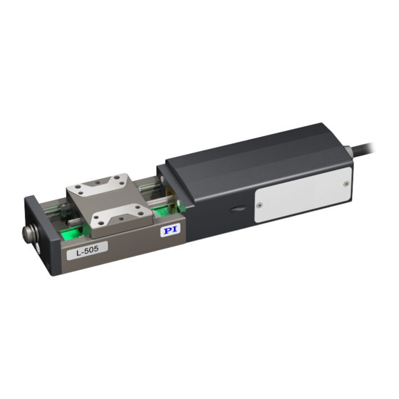
- Page 1 L505M0004EN ‒ 11/26/2018 User Manual L-505.011200 LINEAR STAGE WITH STEPPER MOTOR M O T I O N | P O S I T I O N I N G...
-
Page 2: Table Of Contents
Suitable Electronics..................10 Accessories.......................10 Unpacking........................12 Installation......................... 13 Mounting the L-505.011200................13 Connecting the L-505.011200 to the Protective Earth Conductor....14 Setting Up a Multi-Axis System..............15 Building a Vertical Multi-Axis System............17 Mounting the Load onto the L-505.011200............. 21 Connecting the L-505.011200................23 Startup / Operation.................... - Page 3 CONTENTS L505M0004EN ‒ 11/26/2018 Troubleshooting......................28 10 Transportation......................29 11 Customer Service Department................. 30 12 Technical Data......................31 12.1 Specifications....................31 12.2 Maximum Ratings................... 33 12.3 Ambient Conditions and Classifications............33 12.4 Dimensions...................... 34 13 Old Equipment Disposal................... 35 14 Appendix........................37 14.1 Pin Assignment....................37 14.1.1 Drive Connector................
-
Page 4: Legal Information
With regard thereto, Physik Instrumente (PI) GmbH & Co. KG reserves all rights. The use of any text, images and drawings is permitted only in part and only when indicating the source. -
Page 5: About This Document
L505M0004EN ‒ 11/26/2018 About this Document Objective and Target Group This user manual contains the information needed for the intended use of the L-505.011200. Basic knowledge of closed-loop systems, motion control concepts, and applicable safety measures is assumed. Other Applicable Documents The devices and software tools that are mentioned in this documentation are described in separate manuals. -
Page 6: Symbols Used
Failure to observe can lead to material damage. ► Action to take to avoid the risk. Information Additional information on the L-505.011200 that can affect your application. Figures For better understandability, the colors, proportions and degree of detail in illustrations can deviate from the actual circumstances. - Page 7 2 ABOUT THIS DOCUMENT L505M0004EN ‒ 11/26/2018 b) Enter the login data. The login data is in the [...]_Releasenews_[...].pdf in the Manuals directory on the data storage device. If necessary: Follow the link and register yourself to get the login data. c) Click Login or press the Enter key.
-
Page 8: Safety
► Add all information from the manufacturer such as supplements or technical notes to the user manual. ► If you give the L-505.011200 to a third party, also include this user manual as well as other relevant information provided by the manufacturer. -
Page 9: Product Description
Product Description Product Labeling 4.1.1 Type Plate The type plate is on the plug connector of the L-505.011200. Figure 1: Type plate of the L-505.011200 1. Product number (example) 2. Serial number (example), individual for each L-505.011200 Meaning of the position (counting from the left):... -
Page 10: Overview
Suitable Electronics The L-505.011200 must be connected to suitable electronics that supply the necessary voltage for operating and if required, to evaluate the sensor and limit switch signals. The following electronics are suitable:... - Page 11 4 PRODUCT DESCRIPTION L505M0004EN ‒ 11/26/2018 To order, contact our customer service department (p. 30). M O T I O N | P O S I T I O N I N G...
-
Page 12: Unpacking
Unpacking the L-505.011200 1. Unpack the L-505.011200 with care. 2. When the L-505.011200 was delivered with ESD protective caps on the connections: Do not remove the ESD protective caps. 3. Compare the contents with the scope of delivery according to the contract and the delivery note. -
Page 13: Installation
CAUTION Risk of crushing by moving parts! Risk of minor injuries from crushing between the moving parts of the L-505.011200 or the load and a fixed part or obstacle. ► Use safeguards to protect limbs areas where they could be caught by moving parts. -
Page 14: Connecting The L-505.011200 To The Protective Earth Conductor
► Only use screws and locating pins of the correct length for the respective mounting holes. Mounting the L-505.011200 on a Surface 1. If necessary: Allow access to the mounting holes in the base body of the L-505.011200. Possible measures: ■... -
Page 15: Setting Up A Multi-Axis System
■ Upper positioner: Forms the upper axis of the multi-axis system, is attached to the lower positioner rotated by 90° Tools and Accessories ■ Screws in the scope of delivery of the L-505.011200: ■ 4 screws ISO 4762, M3×6, A2 ■ 2 locating pins ISO 8734, 2m6×8 ■... - Page 16 L-505.011200 or damage to the L-505.011200 or the electronics. ► Install the L-505.011200 so that the cable has a bending radius of ≥35 mm. ► If necessary: Use cables that are approved for recurring mechanical loading (e.g., drag chain cables).
-
Page 17: Building A Vertical Multi-Axis System
6 INSTALLATION L505M0004EN ‒ 11/26/2018 Building a Vertical Multi-Axis System The L-505.011200 can be used as Z axis. A mounting bracket is necessary, see Optional Accessories (p. 10). Designations in these instructions: ■ Horizontal positioner: Forms the horizontal axis of the multi-axis system ■... - Page 18 Unwanted changes in the position of the motion platform can damage the drive, the load or the environment. ► If the L-505.011200 is mounted vertically, make sure that the installed load is lower than the self-locking of the drive. (see Specifications (p.
- Page 19 L-505.011200 or damage to the L-505.011200 or the electronics. ► Install the L-505.011200 so that the cable has a bending radius of ≥35 mm. ► If necessary: Use cables that are approved for recurring mechanical loading (e.g., drag chain cables).
- Page 20 6 INSTALLATION L505M0004EN ‒ 11/26/2018 2. Attach the upper L-505 to the mounting bracket. a) Insert two 2 mm m6 × 8 mm locating pins into the mounting bracket. b) Align the L-505 to the mounting bracket. c) Insert the M3×6 screws into the holes in the upper L-505 and tighten them. M O T I O N | P O S I T I O N I N G...
-
Page 21: Mounting The Load Onto The L-505.011200
6 INSTALLATION L505M0004EN ‒ 11/26/2018 Mounting the Load onto the L-505.011200 Overview 1. Screws 2. Load M O T I O N | P O S I T I O N I N G... - Page 22 ► In the case of multi-axis systems, include the masses of the positioners to be moved when calculating the load. NOTICE Excessively long screws and locating pins Screws and locating pins that are inserted too deeply can damage the L-505.011200. ► Pay attention to the depth of the mounting and locating holes (p. 34).
-
Page 23: Connecting The L-505.011200
L-505.011200 or damage to the L-505.011200 or the electronics. ► Install the L-505.011200 so that the cable has a bending radius of ≥35 mm. ► If necessary: Use cables that are approved for recurring mechanical loading (e.g., drag chain cables). -
Page 24: Startup / Operation
1. Start up the electronics (see the user manual for the electronics). 2. Configure the electronics for the L-505.011200 during startup: ■ If you are using a digital controller from PI: In the PC software, select the entry in the positioner database that matches the L-505.011200 exactly. -
Page 25: Maintenance
■ After 500 operating hours or at least after one 1 year ■ If the L-505.011200 is moved over a small travel range (<20 % of the entire travel range) during industrial operation: After every 2000 motion cycles Performing a Maintenance Run 1. -
Page 26: Moving The Motion Platform By Hand
■ Lubricant for the drive screw: Isoflex Topas 30 ■ Lubricant for the guides: Klüberquiet BQ 72‑72 Relubricating Under laboratory conditions, it is only necessary to relubricate the L-505.011200 in exceptional cases. For continuous industrial use, the lubrication intervals must be defined individually. -
Page 27: Cleaning
(p. 30). NOTICE Damage due to unsuitable cleaning agents! Some cleaning agents can cause rusting on the L-505.011200 or dissolve plastics, paints or adhesives. ► Do not clean with water or acetone. Cleaning the L-505.011200 1. Dampen the cloth with the cleaning agent or disinfectant. -
Page 28: Troubleshooting
Reduced positioning accuracy ► Make sure that the self‐locking of the When the L-505.011200 is mounted vertically: Load exceeds the self-locking of the drive drive (p. 31) is not exceeded. Mount the L‐505.011200 onto an even sur‐... -
Page 29: Transportation
33). 2. Pack the L-505.011200 in the original packaging. 3. If the L-505.011200 is to be sent, use a stable outer box. M O T I O N | P O S I T I O N I N G... -
Page 30: Customer Service Department
L505M0004EN ‒ 11/26/2018 Customer Service Department For enquiries and orders, contact your PI miCos representative or send us an email. If you have any questions concerning your system, provide the following information: ■ Product and serial numbers of all products in the system ■... -
Page 31: Technical Data
12 TECHNICAL DATA L505M0004EN ‒ 11/26/2018 Technical Data 12.1 Specifications Unit Toler- L-505.011200 ance Active axes Travel range Integrated sensor Sensor signal Sensor resolution System resolution 2500 Minimum incremental motion µm typ. Unidirectional repeatability µm typ. Bidirectional repeatability µm typ. - Page 32 12 TECHNICAL DATA L505M0004EN ‒ 11/26/2018 Unit Toler- L-505.011200 ance Guide type Ball bearings Drive force Holding force (passive) Permissible lateral force max. Load capacity max. Permissible torque in θx N·m max. Permissible torque in θY N·m max. Permissible torque in θZ N·m...
-
Page 33: Maximum Ratings
48 V ‑ 12.3 Ambient Conditions and Classifications The following ambient conditions and classifications for the L-505.011200 must be observed: Area of application For indoor use only Maximum altitude 2000 m above msl Relative humidity 20 to 80%, not condensing Storage temperature -20 °C to +70 °C... -
Page 34: Dimensions
Dimensions in mm. Note that the decimal places are separated by a comma in the drawings. Figure 3: Mounting holes in the L-505.011200's motion platform Dimensions in mm. Note that the decimal places are separated by a comma in the drawings. -
Page 35: Old Equipment Disposal
In order to fulfil the responsibility as the product manufacturer, PI miCos undertakes environmentally correct disposal of all PI miCos equipment free of charge, if it was made available to the market after August 13, 2005. Any old PI miCos equipment can be sent free of charge to the following address:... - Page 36 L505M0004EN ‒ 11/26/2018 Glossar Load Capacity Maximum load in the vertical direction when the L-505.011200 is mounted horizontally. The contact point of the load is at the center of the motion platform. Max. push/pull force Maximum force in the direction of motion. The L-505.011200 could exert higher forces, however will shorten the lifetime.
-
Page 37: Appendix
14 APPENDIX L505M0004EN ‒ 11/26/2018 Appendix 14.1 Pin Assignment 14.1.1 Drive Connector Figure 4: HD Sub-D 26 (m) Function Input: Motor voltage, phase A, + Not connected Input: Motor voltage, phase A, - Not connected Input: Motor voltage, phase B, + Not connected Input: Motor voltage, phase B, - Not connected... -
Page 38: Drive Properties
Not connected Not connected Ground Not connected 14.2 Drive properties If you use third-party control electronics, it may be necessary to adapt the following operating parameters in the L-505.011200. 14.3 Reference point switch specifications Type Hall sensor Supply voltage +5 V... - Page 39 14 APPENDIX L505M0004EN ‒ 11/26/2018 Figure 5: L-505 at the negative limit switch. Figure 6: L-505 at the positive limit switch. M O T I O N | P O S I T I O N I N G...
-
Page 40: Eu Declaration Of Conformity
15 EU DECLARATION OF CONFORMITY L505M0004EN ‒ 11/26/2018 EU Declaration of Conformity An EU Declaration of Conformity was issued for the L-505.011200 in accordance with the following European directives: ■ EMC Directive ■ RoHS Directive The applied standards certifying the conformity are listed below.
Need help?
Do you have a question about the L-505.011200 and is the answer not in the manual?
Questions and answers