
Related Manuals for PI L-417.XX9232B Series


Summary of Contents for PI L-417.XX9232B Series
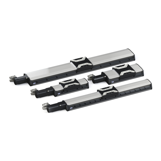
- Page 1 L417M0010EN ‒ 7/9/2019 User Manual L-417.XX9232B HIGH-LOAD LINEAR STAGE M O T I O N | P O S I T I O N I N G...
-
Page 2: Table Of Contents
CONTENTS L417M0010EN ‒ 7/9/2019 Contents Legal Information......................4 About this Document....................5 Objective and Target Group................5 Explanation of Symbols..................5 2.2.1 Typographic Conventions..............5 2.2.2 Symbols Used..................5 Figures........................ 6 Downloading Manuals..................6 Safety..........................7 Intended Use...................... 7 General Safety Instructions................7 Organizational Measures.................. - Page 3 CONTENTS L417M0010EN ‒ 7/9/2019 Troubleshooting......................25 10 Transportation......................26 11 Customer Service Department................. 27 12 Technical Data......................28 12.1 Specifications....................28 12.2 Maximum Ratings................... 30 12.3 Ambient Conditions and Classifications............30 12.4 Dimensions...................... 31 13 Old Equipment Disposal................... 33 14 Appendix........................34 14.1 Pin Assignment....................34 14.1.1 Drive Connector................
-
Page 4: Legal Information
With regard thereto, Physik Instrumente (PI) GmbH & Co. KG reserves all rights. The use of any text, images and drawings is permitted only in part and only when indicating the source. -
Page 5: About This Document
This user manual contains the information needed for the intended use of the L-417.xx9232B. Basic knowledge of closed-loop systems, motion control concepts, and applicable safety measures is assumed. Explanation of Symbols This chapter explains the symbols and markings used by PI in their user manuals. 2.2.1 Typographic Conventions Symbol / Label... -
Page 6: Figures
(p. 27). Downloading Manuals 1. Open the website www.pi.ws. 2. If the product was shipped with a data storage device: Log into the website: a) Click Login. b) Enter the login data. The login data is in the [...]_Releasenews_[...].pdf in the Manuals directory on the data storage device. -
Page 7: Safety
► Always keep this user manual available with the L-417.xx9232B. The latest versions of the user manuals can be downloaded (p. 6) at www.pi.ws. ► Add all information from the manufacturer such as supplements or technical notes to the user manual. -
Page 8: Product Description
4 PRODUCT DESCRIPTION L417M0010EN ‒ 7/9/2019 Product Description Model Overview High-load linear stage, xx mm travel range, 166 mm width, 450 N load capacity, incremental rotary encoder with A/B quadrature signal transmission, 20000 counts/ rev, holding brake, synchronous servo motor, to 320 V Product number Travel range: xx L-417.059232B... -
Page 9: Type Plate
4 PRODUCT DESCRIPTION L417M0010EN ‒ 7/9/2019 4.2.1 Type Plate Figure 2: Type plate of the L-417.xx9232B 1. Data matrix code (example; contains the serial number) 2. Product number (example) 3. Serial number (example), individual for each L-417.xx9232B Meaning of the position (counting from the left): 1 = internal information, 2 and 3 = year of manufacture, 4 to 9 = consecutive numbers... -
Page 10: Overview
4 PRODUCT DESCRIPTION L417M0010EN ‒ 7/9/2019 Overview Figure 3: Elements of the L-417.xx9232B 1. Base body 2. Motion platform 3. Drive 4. Holding brake 5. Drive and sensor connector 6. Connectors for limit switch signals and purge air 7. Grease nipple for relubricating the drive screw 4.4.1 Base Body The base body is the basis of the positioner. -
Page 11: Holding Brake
4 PRODUCT DESCRIPTION L417M0010EN ‒ 7/9/2019 The drive comprises the following subassembly (subassemblies): Motor The motor generates the torque required for the dynamics of the motion platform. Rotary encoder The rotary encoder measures the motor shaft's angle of rotation. This signal can be used by suitable electronics for commutating the motor and for calculating the position of the motion platform after a reference move . - Page 12 4 PRODUCT DESCRIPTION L417M0010EN ‒ 7/9/2019 Passive dust protection The passive dust protection consists of covering strips that seal the openings on the side of the L-417.xx9232B's base body and therefore reduces the amount of dust that can penetrate. Active dust protection The active dust protection consists of a purge air connector on the base body of the L-417.xx9232B, which creates a slight overpressure in the L-417.xx9232B and therefore reduces the amount of dust that can penetrate.
-
Page 13: Direction Of Motion
4 PRODUCT DESCRIPTION L417M0010EN ‒ 7/9/2019 Direction of Motion Positive Direction of Motion Negative Limit Switch Positive Limit Switch Figure 4: Schematic representation of the direction of motion and limit switches. The exact position of the limit switches may vary. Suitable Electronics The L-417.xx9232B must be connected to suitable electronics that supply the necessary voltage for operating and if required, to evaluate the sensor and limit switch signals. -
Page 14: Unpacking
5 UNPACKING L417M0010EN ‒ 7/9/2019 Unpacking Unpacking the L-417.xx9232B 1. Unpack the L-417.xx9232B with care. Hold the L-417.xx9232B by its base body only. 2. Compare the contents with the scope of delivery according to the contract and the delivery note. 3. -
Page 15: Installation
6 INSTALLATION L417M0010EN ‒ 7/9/2019 Installation Mounting the L-417.xx9232B Overview Figure 5: Mounting the L-417.xx9232B onto an underlying surface Tools and Accessories Screw set for mounting the L-417.xx9232B (p. 9) ■ ■ Suitable screwdriver Requirements You have read and understood the general safety instructions (p. -
Page 16: Connecting The L-417.Xx9232B To The Protective Earth Conductor
6 INSTALLATION L417M0010EN ‒ 7/9/2019 CAUTION Risk of crushing by moving parts! Risk of minor injuries from crushing between the moving parts of the L-417.xx9232B or the load and a fixed part or obstacle. ► Use safeguards to protect limbs in areas where they could be caught by moving parts. ►... - Page 17 6 INSTALLATION L417M0010EN ‒ 7/9/2019 Overview Figure 6: Protective earth connector on the L-417.xx9232B 1. Connector for the protective earth conductor on the L-417.xx9232B, indicated by the protective earth symbol 2. Safety washer 3. Flat washer 4. Protective earth conductor lug 5.
-
Page 18: Mounting The Load Onto The L-417.Xx9232B
6 INSTALLATION L417M0010EN ‒ 7/9/2019 4. Make sure that the contact resistance is <0.1 Ω at 25 A at all connection points relevant for attaching the protective earth conductor. Mounting the Load onto the L-417.xx9232B Overview Figure 7: Mounting the load onto the L-417.xx9232B 1. -
Page 19: Connecting The L-417.Xx9232B
► Make sure that the electronics support the drive type of the L-417.xx9232B and has been configured accordingly. ► Use cables from PI miCos only to connect the L-417.xx9232B to the electronics. ► Pay attention to correct pin assignment (p. - Page 20 6 INSTALLATION L417M0010EN ‒ 7/9/2019 Permissible pressure: 2 to 6 bar (200 to 600 kPa) c) Rotary encoder connector d) Drive connector 3. Secure the connectors against unintentional removal. If necessary: Turn the drive and encoder connector carefully to a position suitable for your installation conditions.
-
Page 21: Startup / Operation
7 STARTUP / OPERATION L417M0010EN ‒ 7/9/2019 Startup / Operation Starting and Operating the L-417.xx9232B Requirements You have read and understood the general safety instructions (p. ✓ For startup with a load or in a multi-axis system: You have installed the L-417.xx9232B ✓... - Page 22 1. Start the electronics (see the user manual for the electronics). 2. Configure the electronics for the L-417.xx9232B during startup: ■ If you are using a digital controller from PI: In the PC software, select the entry in the positioner database that matches the L-417.xx9232B exactly.
-
Page 23: Maintenance
8 MAINTENANCE L417M0010EN ‒ 7/9/2019 Maintenance NOTICE Damage due to improper maintenance! Improper maintenance can lead to misalignment and failure of the L-417.xx9232B. ► Loosen screws only according to the instructions in this manual or the instructions of our customer service department (p. 27). -
Page 24: Moving The Motion Platform By Hand
8 MAINTENANCE L417M0010EN ‒ 7/9/2019 NOTICE Damage due to unsuitable cleaning agents! Some cleaning agents can cause rusting on the L-417.xx9232B or dissolve plastics, paints or adhesives. ► Do not clean with water or acetone. Cleaning the L-417.xx9232B 1. Dampen the cloth with the cleaning agent or disinfectant. 2. -
Page 25: Troubleshooting
► Defective electronics ► Check the electronics. Motion platform has triggered the limit ► If you are using a controller from PI: Switch on switch the servo mode for the affected axis again in the PC software. ► Command the axis to move away from the limit switch. -
Page 26: Transportation
10 TRANSPORTATION L417M0010EN ‒ 7/9/2019 Transportation Preparing the L-417.xx9232B for Transportation 1. Pay attention to the ambient conditions and classifications (p. 30). 2. Pack the L-417.xx9232B in the original packaging. 3. If the L-417.xx9232B is to be sent, use a stable outer box. M O T I O N | P O S I T I O N I N G... -
Page 27: Customer Service Department
L417M0010EN ‒ 7/9/2019 Customer Service Department For enquiries and orders, contact your PI miCos representative or send us an email. If you have any questions concerning your system, provide the following information: ■ Product and serial numbers of all products in the system ■... -
Page 28: Technical Data
12 TECHNICAL DATA L417M0010EN ‒ 7/9/2019 Technical Data 12.1 Specifications Motion L-417.05 L-417.09 L-417.13 L-417.17 Unit Toler- ance Active axes Travel range Pitch / yaw ±14 ±19 ±29 ±35 μrad max. Straightness / flat- ±2.5 ±4 ±6 ±8 μm max. ness Velocity, unloaded mm/s max. - Page 29 12 TECHNICAL DATA L417M0010EN ‒ 7/9/2019 Mechanical properties L-417.xxxxxx L-417.xxxxxxB Unit Toler- ance Guide type Recirculating ball Recirculating ball bearing guide bearing guide Drive screw type Ball screw Ball screw Holding brake – Electromagnetic safe- ty brake Drive screw pitch Push/pull force, power on max.
-
Page 30: Maximum Ratings
12 TECHNICAL DATA L417M0010EN ‒ 7/9/2019 Miscellaneous L-417 Unit Toler- ance Operating temperature range 5 to 40 °C Material Aluminum, black anodized stainless steel Overall mass L-417.05 (102 mm travel range): 9.3 ±5 % L-412.09 (204 mm travel range): 10.8 L-412.13 (305 mm travel range): 12.2 L-412.17 (407 mm travel range): 13.7 L-412.21 (508 mm travel range): 15.1... -
Page 31: Dimensions
12 TECHNICAL DATA L417M0010EN ‒ 7/9/2019 Area of application For indoor use only Maximum altitude 2000 m above msl Relative humidity Max. 80 % for temperatures to 31 °C, linearly decreasing to 50 % at 40 °C Storage temperature -25 °C to 55 °C Transport temperature -25 °C to 70 °C Overvoltage category... - Page 32 12 TECHNICAL DATA L417M0010EN ‒ 7/9/2019 4 x M6 4 x M6 4 x M6 4 H7x7 4 H7x7 4 H7x7 Figure 10: Motion platform of the L-417.xx9232B: Dimensions and mounting holes Dimensions in mm. Note that the decimal places are separated by a comma in the drawings. M O T I O N | P O S I T I O N I N G...
-
Page 33: Old Equipment Disposal
In order to fulfil the responsibility as the product manufacturer, PI miCos undertakes environmentally correct disposal of all PI miCos equipment free of charge, if it was made available to the market after August 13, 2005. Any old PI miCos equipment can be sent free of charge to the following address:... -
Page 34: Appendix
14 APPENDIX L417M0010EN ‒ 7/9/2019 Appendix 14.1 Pin Assignment 14.1.1 Drive Connector Figure 11: M23 8 (f) Signal Function Phase 1 Protective earth Phase 3 Phase 2 BR + Holding brake, +24 V DC BR - Holding brake, GND Not connected Not connected 14.1.2 Rotary Encoder Connector 16 17... -
Page 35: 14.1.3 Limit Switch Connector
14 APPENDIX L417M0010EN ‒ 7/9/2019 Signal Function Output: Sensor signal B B inv Output: Sensor signal B inverted Output: Sensor signal A A inv Output: Sensor signal A inverted Output: Sensor signal Z Z inv Output: Sensor signal Z inverted Ground THERM+ Output: Temperature sensor... -
Page 36: Limit Switch Specifications
14 APPENDIX L417M0010EN ‒ 7/9/2019 14.2 Limit Switch Specifications Type Hall sensor Supply voltage +5 V Signal output 0 V / +5 V (TTL level) Signal logic N/C contact, NPN Figure 12: L-417 at the negative limit switch. Figure 13: L-417 at the positive limit switch. 14.3 PTC Temperature Sensor The L-417.xx9232B is equipped with a PTC temperature sensor to prevent the motor from... -
Page 37: Holding Brake Specifications
14 APPENDIX L417M0010EN ‒ 7/9/2019 π 2π 3π 4π Figure 14: Motor phases (top) and signal output to the commutation tracks (bottom) 14.5 Holding Brake Specifications Parameters Value Supply voltage 24 V Power requirement 350 mA (min) Static braking torque 1.42 Nm Release brake delay 35 ms... -
Page 38: Eu Declaration Of Conformity
15 EU DECLARATION OF CONFORMITY L417M0010EN ‒ 7/9/2019 EU Declaration of Conformity An EU Declaration of Conformity was issued for the L-417.xx9232B in accordance with the following European directives: ■ Low Voltage Directive ■ EMC Directive ■ RoHS Directive The standards applied for certifying conformity are listed below. ■... - Page 39 Each limit switch sends its signal to the controller on a dedicated line. The controller then interrupts the motion avoiding that the positioner moves until the hard stop and gets damaged. PI positioners have mechanical, noncontact optical or Hall-effect limit switches. Load Capacity Maximum load in the vertical direction when the L-417.xx9232B is mounted horizontally.
- Page 40 L417M0010EN ‒ 7/9/2019 Travel range The maximum possible travel range is limited by the length of the drive screw. A possible gap between the limit switches determines the travel range. M O T I O N | P O S I T I O N I N G...
Need help?
Do you have a question about the L-417.XX9232B Series and is the answer not in the manual?
Questions and answers