Table of Contents
Advertisement
Quick Links
Advertisement
Table of Contents

Related Manuals for THORLABS KT120


Summary of Contents for THORLABS KT120
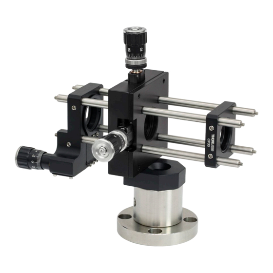
- Page 1 KT120(/M) Fiber Launch System: Free Space User Guide...
-
Page 3: Table Of Contents
4.7. Step 7: Optical Power Measurement ................6 4.7.1. Goals of this Step ........................6 4.7.2. Procedure ..........................7 4.8. Step 8: Assembly of the Z Translator with the KT120(/M) .......... 7 4.8.1. Goals of this Step ........................7 4.8.2. Procedure ..........................7 4.8.3. -
Page 4: Chapter 1 Warning Symbol Definitions
Fiber Launch System: Free Space Chapter 1: Warning Symbol Definitions Chapter 1 Warning Symbol Definitions Below is a list of warning symbols you may encounter in this manual or on your device. Symbol Description Direct Current Alternating Current Both Direct and Alternating Current Earth Ground Terminal Protective Conductor Terminal Frame or Chassis Terminal... -
Page 5: Chapter 2 Safety
IR viewers and the appropriate experience to work safely with intense IR laser beams. If you have any questions please call Thorlabs for technical support. Many fiber launching applications will require an optical isolator to prevent back reflection off the input end of the fiber from reaching the laser. -
Page 6: Chapter 3 Recommended Set-Up
The KT120(/M) has an optical axis that is 3.69” (85.6 mm for the KT120/M). This “Operating Instruction” assumes that the height of your laser beam is from 3.57” to 3.81” above the surface of your optical bench. If you need assistance resetting the height of your laser beam please call Thorlabs for technical support. -
Page 7: Chapter 4 Operating Instructions
The position of the Z translator control needs to be set to the middle of its range. If a fiber optic cable is attached to the KT120(/M) it needs to be removed and set aside until it is specifically called for later in these instructions. -
Page 8: Procedure
Close down on the iris diaphragm that is at the input end of the launch system. Place the KT120(/M) in the laser beam with the iris as the input end. For ease of alignment later on it is recommended that the KT120(/M) be positioned as close to the last mirror mount (Mirror “B”, in Figure F) as possible. -
Page 9: Procedure
While looking at the spot on the input iris use Mirror “A” to move the laser beam a small amount in the same direction as the error that is seen on output aperture of the KT120(/M). In other words if the laser beam is low on the output aperture of the KT120(/M) then use Mirror “A”... -
Page 10: Procedure
This step details the assembly and alignment of the Z translator that houses the input end of the connectorized fiber optic cable with the KT120(/M) launch system. Using the fact that the end of the fiber is partially reflective the... -
Page 11: Step 9: Optimizing Coupling Efficiency
“B” while tweaking the transmission using the XY controls. First, one angular control will be chosen to be stepped in one direction. The XY controls of the KT120(/M) will then be used to maximize the efficiency of the system. - Page 12 Fiber Launch System: Free Space Chapter 4: Operating Instructions Figure F The recommended setup for the KT120(/M). Two mirrors are ideal for aligning the laser beam with the optical axis of the KT120(/M) Fiber Launch System. Page 9 Rev A, July 30, 2021...
-
Page 13: Chapter 5 Regulatory
Waste Treatment is Your Own Responsibility If you do not return an “end of life” unit to Thorlabs, you must hand it to a company specialized in waste recovery. Do not dispose of the unit in a litter bin or at a public waste disposal site. -
Page 14: Chapter 6 Thorlabs Worldwide Contacts
Fiber Launch System: Free Space Chapter 6: Thorlabs Worldwide Contacts Chapter 6 Thorlabs Worldwide Contacts For technical support or sales inquiries, please visit us at www.thorlabs.com/contact for our most up-to-date contact information. USA, Canada, and South America UK and Ireland Thorlabs, Inc. - Page 15 www.thorlabs.com...
Need help?
Do you have a question about the KT120 and is the answer not in the manual?
Questions and answers