
Related Manuals for THORLABS DDS300


Summary of Contents for THORLABS DDS300
- Page 1 DDS300(/M) Direct Drive Translation Stage User Guide Original Instructions HA0324T...
-
Page 2: Table Of Contents
Chapter 5 Specification and Accessories ............... 16 5.1 Specification ..................16 5.2 Accessories List ................17 Chapter 6 Using the Legacy APT Software ............. 18 Chapter 7 Regulatory ....................23 Chapter 8 Thorlabs Worldwide Contacts ..............25 Page 0 ETN013636-D02... -
Page 3: Chapter 1 Introduction
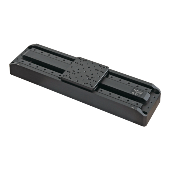
Chapter 1 Introduction Chapter 1 Introduction The Thorlabs’ DDS300 low-profile, direct-drive stage provides 300 mm of travel with 100 nm minimum step size and a maximum speed of 400 mm/s. The stage is ideal for applications that require high speeds and high positioning accuracy, including automated alignment, surface inspection, mapping, and probing. -
Page 4: Chapter 2 Safety
DDS300 Direct Drive Translation Stage Chapter 2 Safety 2.1 Safety Information For the continuing safety of the operators of this equipment, and the protection of the equipment itself, the operator should take note of the Warnings, Cautions and Notes throughout this handbook and, where visible, on the product itself. -
Page 5: Chapter 3 Installation
Chapter 3 Installation Chapter 3 Installation 3.1 Unpacking Note During handling or shipping, the moving platform must be constrained to avoid damage to the bearings. Retain the packing in which the unit was shipped, for use in future transportation. Two handles are shipped with the unit to assist in handling. These handles should be fitted to the center hole at either end of the stage. -
Page 6: Mounting
DDS300 Direct Drive Translation Stage Mounting Warning The safety of any system incorporating this equipment is the responsibility of the person performing the installation. 3.3.1 Vertical Mounting Warning The stage is not suitable for mounting in a vertical (Z-axis) configuration. -
Page 7: Mounting The Stage To The Work Surface
3.3.4 Mounting the Stage to the Work Surface The DDS300 stage is mounted to the work surface by four M6 x 25 mm (1/4”-20 x 1”) screws. The mounting holes are accessed from the top of the stage as shown below. - Page 8 DDS300 Direct Drive Translation Stage Caution When mounting the stage to the worksurface, use only the holes in the end of the stage as shown above. The performance of the stage could be affected if the mounting surface is not flat. Pads at the end and in the middle are not on the same plane.The middle mounting holes should be used exclusively in cases when the ends have no...
-
Page 9: Electrical Connections
Electrical Connections The stage must be driven by a Thorlabs BBD series and RBD201 controllers. Connect the motor leads to the MOTOR DRIVE connectors, and the encoder feedback leads to the FEEDBACK connectors. Ensure that the motor drive and feedback leads for each motor are connected to the correct channel. - Page 10 12 Enc Index + 5 QB - 13 QB + 6 QA - 14 QA + 7 5 V 15 Not Used 8 5 V Fig. 3.5 DDS300 Motor Drive and Feedback Flying Lead Pin Out Details Page 8 ETN013636-D02...
-
Page 11: Chapter 4 Operation
Failure to do this could result in stages not being recognized by the latest controllers. The DDS300 stage is designed to be driven by the Thorlabs BBD30x or RBD201 Brushless DC Motor Controllers. -
Page 12: General Operation
- see the Kinesis Helpfile for more information. 1) If it is not already running, start the Kinesis software - Start/Programs/Thorlabs/Kinesis/ Kinesis.The server reads in the stage and controller information on boot up and the GUI panel shown below is displayed. - Page 13 Chapter 4 Operation Note The MOTOR DRIVE connectors for each channel/axis contain an EEPROM, which stores the factory default settings for the set up parameters. When the stage is connected, these settings are loaded into the controller on start up, and are tuned for loads up to the 2.0 kg (4.4 lb) maximum, at speeds up to 100 mm/s.
- Page 14 DDS300 Direct Drive Translation Stage 3) Create a Custom Settings Group (see the Kinesis helpfile for more information) and then adjust the PID settings to fine tune the control loop for your application. Refer to the handbook supplied with the BBD301 control unit for more details on PID settings.
-
Page 15: Stopping The Stage
Chapter 4 Operation See the manual supplied with the controller unit for more information. Note For a given load, a deviation of typically ±10% from the values quoted may be necessary. To optimize parameters proceed as follows: Stage overshoots the intended position- reduce the Integral term and increase the Derivative and Proportional terms. -
Page 16: Position Error Messages
The product is maintenance free up to 5 million cycles. If any problems occur, the user should contact the local Thorlabs tech support for more information. After 5 million cycles, a replacement of the internal flexible cable, and a relubrication of the bearing carriers is recommended. -
Page 17: Transportation
After the obstruction to be removed, the associated channel of the controller should first be disabled to clear any fault codes, then re-enabled. In the event of a breakdown, or malfunction of the product please contact Thorlabs Tech Support. Contact details are contained in Chapter C. -
Page 18: Chapter 5 Specification And Accessories
DDS300 Direct Drive Translation Stage Chapter 5 Specification and Accessories Specification Parameter Value Travel Range 300 mm (11.81") Max Speed 400 mm/s Max Acceleration 10,000 mm/s Bidirectional Repeatability ±0.25 µm Backlash Encoder Resolution 50 nm Min Incremental Movement 100 nm 10.0 kg (22.0 lb) -
Page 19: Accessories List
Alternatively the load, acceleration and duty cycle should be reduced from the maximum values. Some trial and error in setting these values may be necessary before the ideal settings are attained. Please contact your local Thorlabs tech support office for more details. -
Page 20: Chapter 6 Using The Legacy Apt Software
PID loop parameter settings to fine tune the response - see the following pages for more information. 2) If it is not already running, start the APT User utility - Start/Programs/Thorlabs/APT User/ APT User The APT server reads in the stage and controller information on boot up and the GUI panel shown below is displayed. - Page 21 Chapter 5 Specification and Accessories Note The MOTOR DRIVE connectors for each channel/axis contain an EEPROM, which stores the factory default settings for the set up parameters. When the stage is connected, these settings are loaded into the controller on start up, and are tuned for loads up to the 2.0 kg (4.4 lb) maximum, at speeds up to 100 mm/s.
- Page 22 DDS300 Direct Drive Translation Stage 4) Adjust the PID settings to fine tune the control loop for your application. Refer to the handbook supplied with the BBD301 control unit for more information. Caution Default PID values for 2 kg load placed at the centre of the top plate have already been optimized and stored within the stage, and these are loaded into the controller on power up.
- Page 23 Appendix A Using the Legacy APT Software See the manual supplied with the controller unit for more information. Note For a given load, a deviation of typically ±10% from the values quoted may be necessary. To optimize parameters proceed as follows: Stage overshoots the intended position- reduce the Integral term and increase the Derivative and Proportional terms.
- Page 24 DDS300 Direct Drive Translation Stage Position Error Messages Caution The maximum velocity at which the encoder can operate is approximately 400 mm/ sec. Above this speed, encoder pulses may be lost and, as a result, the position readout becomes incorrect. This renders normal operation impossible because phase commutation of the motor is also based on the encoder reading.
-
Page 25: Chapter 7 Regulatory
Appendix B Regulatory Appendix B Regulatory B.1 Declarations Of Conformity B.1.1 For Customers in Europe See Section B.2. B.1.2 For Customers In The USA This equipment has been tested and found to comply with the limits for a Class A digital device, pursuant to part 15 of the FCC rules. - Page 26 DDS300 Direct Drive Translation Stage CE Declaration Page 24 ETN013636-D02...
-
Page 27: Chapter 8 Thorlabs Worldwide Contacts
Waste treatment is your own responsibility. "End of life" units must be returned to Thorlabs or handed to a company specializing in waste recovery. Do not dispose of the unit in a litter bin or at a public waste disposal site. - Page 28 www.thorlabs.com...
Need help?
Do you have a question about the DDS300 and is the answer not in the manual?
Questions and answers