Sign In
Upload
Manuals
Brands
Keba Manuals
Control Unit
Kemro K2
Keba Kemro K2 Manuals
Manuals and User Guides for Keba Kemro K2. We have
2
Keba Kemro K2 manuals available for free PDF download: User Manual, Project Engineering Manual
Keba Kemro K2 User Manual (234 pages)
KePlast.HMI.KVB Visualization
Brand:
Keba
| Category:
Controller
| Size: 2.89 MB
Table of Contents
Table of Contents
5
1 Introduction
17
Purpose of the Document
17
Target Groups, Pre-Conditions
17
Notes on this Document
17
Contents of Document
17
Not Contained in this Document
18
Documentation for Further Reading
18
2 Safety Notes
19
Representation
19
General Safety Instructions
20
3 Operation and Display
21
Basic Layout
21
Status Bar
22
Status Icons
23
Active Movements
24
Mask Navigation
26
Mask Hierarchy
27
Key Assignments on the Panel
29
Function Keys
29
Numerical /Alpha-Numerical Keypad
29
Arrow Key Pad
30
Keys for Setting the Operating Mode
31
Further Keys Operating the Injection Molding Machine
31
Tabs
32
Quick Access Panel and Favourite Masks
33
Actual Value Panel
34
Opening Mask Help
36
Opening Context Help
36
Mask Print / Create Screenshot
37
Creating a Status Report
37
User Login and Logout
38
Favourite Masks
38
4 Description of the Operating Masks
39
Overview Mask
39
Purpose
39
Description of the Mask
39
Description of the Elements
39
Overview Vertical
41
Purpose
41
Description of the Mask
41
Description of the Elements
42
Mold - Tab Profile
44
Purpose
44
Description of the Mask
44
Description of the Elements
45
Mold - Tab Graphic
46
Purpose
46
Description of the Mask
46
Description of the Elements
47
Mold Setup - Tab1
47
Purpose
47
Description of the Mask
47
Description of the Elements
48
Mold Setup - Tab2
50
Purpose
50
Description of the Mask
50
Description of the Elements
50
Mold Setup Advanced - Tab1
52
Purpose
52
Description of the Mask
52
Description of the Elements
52
Mold Setup Advanced - Tab2
54
Purpose
54
Description of the Mask
54
Description of the Elements
55
Mold Setup Advanced - Tab Mold Control
55
Purpose
55
Description of the Mask
56
Description of the Elements
56
Mold Height Adjust
57
Purpose
57
Description of the Mask
57
Description of the Elements
58
Lubrication
60
Purpose
60
Description of the Mask
60
Description of the Elements
60
Mold Options - Tab Rotary Table
61
Purpose
61
Description of the Mask
61
Description of the Elements
62
Mold Options - Tab Slide Table
62
Purpose
62
Description of the Mask
63
Description of the Elements
63
Mold Options - Tab Automatic Safety Gate
64
Purpose
64
Description of the Mask
64
Description of the Elements
65
Mold Options - Tab Coining / Venting
66
Purpose
66
Description of the Mask
66
Description of the Elements
67
Ejector and Airvalves
68
Purpose
68
Description of the Mask
68
Description of the Elements
69
Ejector - Tab Graphic
71
Purpose
71
Description of the Mask
71
Description of the Elements
72
Ejector Setup
72
Purpose
72
Description of the Mask
72
Description of the Elements
73
Ejector Setup Advanced
74
Purpose
74
Description of the Mask
74
Description of the Elements
75
Cores
76
Purpose
76
Description of the Mask
76
Description of the Elements
77
Core Setup - Tab1
79
Purpose
79
Description of the Mask
79
Description of the Elements
79
Core Setup - Tab2
80
Purpose
80
Description of the Mask
81
Description of the Elements
81
Core Setup Advanced - Tab1
82
Purpose
82
Description of the Mask
83
Description of the Elements
83
Core Setup Advanced - Tab2
84
Purpose
84
Description of the Mask
84
Description of the Elements
85
Core Ramp Adjust
85
Purpose
85
Description of the Mask
85
Description of the Elements
86
Injection - Tab Profile
86
Purpose
86
Description of the Mask
87
Description of the Elements
87
Inject - Tab Graphic
88
Purpose
88
Description of the Elements
89
Plasticize and Decompression - Tab Profile
90
Purpose
90
Description of the Mask
90
Description of the Elements
90
Plasticize - Tab Graphic
91
Purpose
91
Description of the Mask
91
Description of the Elements
92
Inject Setup
92
Purpose
92
Description of the Mask
92
Description of the Elements
93
Inject Setup Advanced - Tab1
95
Purpose
95
Description of the Mask
95
Description of the Elements
95
Inject Setup Advanced - Tab2
96
Purpose
96
Description of the Mask
96
Description of the Elements
97
Inject Setup Advanced - Tab Inject Control
98
Purpose
98
Description of the Mask
98
Description of the Elements
98
Inject Graph
100
Purpose
100
Description of the Mask
100
Description of the Elements
101
Inject Graph Settings
101
Purpose
101
Description of the Mask
102
Description of the Elements
102
Valve Gates - Tab1
103
Purpose
103
Description of the Mask
103
Description of the Elements
103
Valve Gates - Tab2
104
Purpose
104
Description of the Mask
105
Description of the Elements
105
Valve Gates - Tab Setup
106
Purpose
106
Description of the Mask
107
Description of the Elements
107
Nozzle - Tab Profile
107
Purpose
107
Description of the Elements
109
Nozzle - Tab Graphic
110
Purpose
110
Description of the Mask
110
Description of the Elements
111
Nozzle Setup
112
Purpose
112
Description of the Mask
112
Description of the Elements
112
Nozzle Setup Advanced
113
Purpose
113
Description of the Mask
113
Description of the Elements
114
Nozzle Options
115
Purpose
115
Description of the Mask
115
Description of the Elements
116
Heating Nozzle
117
Purpose
117
Description of the Mask
117
Description of the Elements
118
Heating Nozzle Setup - Tab1
119
Purpose
119
Description of the Mask
119
Description of the Elements
119
Heating Nozzle Setup - Tab2
121
Purpose
121
Description of the Mask
121
Description of the Elements
121
Heating Mold - Hot Runner
122
Purpose
122
Description of the Mask
122
Description of the Elements
123
Hot Runner Setup
124
Purpose
124
Description of the Mask
125
Description of the Elements
125
Hot Runner Setup Advanced
126
Purpose
126
Description of the Mask
126
Description of the Elements
127
Alarms
127
Purpose
127
Description of the Mask
127
Description of the Elements
128
Production Settings - Tab1
128
Purpose
128
Description of the Mask
128
Description of the Elements
129
Production Settings - Tab2
131
Purpose
131
Description of the Mask
131
Description of the Elements
132
Production Settings - Tab3
132
Purpose
132
Description of the Mask
132
Mold Data
133
Purpose
133
Description of the Mask
133
Description of the Elements
134
Export
135
Purpose
135
Description of the Mask
135
Description of the Elements
135
Energy Monitor
136
Purpose
136
Description of the Mask
136
Description of the Elements
137
Energy Chart (by Shot)
137
Purpose
137
Description of the Mask
137
Description of the Elements
138
Energy Chart (by Time)
139
Purpose
139
Description of the Mask
139
Description of the Elements
140
Flex IO Mask
140
Purpose
140
Description of the Mask
140
Description of the Elements
141
Flex IO Systemvariables
142
Purpose
142
Description of the Mask
142
Description of the Elements
143
Process Data Protocol (PDP)
143
Purpose
143
Description of the Mask
143
Description of the Elements
144
Statistical Process Control (SPC)
145
Purpose
145
Description of the Mask
145
Description of the Elements
146
SPC Settings
147
Purpose
147
Description of the Mask
147
Description of the Elements
148
SPC Variable Setup
148
Purpose
148
Description of the Mask
149
Description of the Elements
149
IO Monitor Overview
150
Purpose
150
Description of the Mask
150
Description of the Elements
150
IO Monitor Digital Inputs
151
Purpose
151
Description of the Mask
151
Description of the Elements
152
IO Monitor Digital Outputs
152
Zweck
152
Description of the Mask
152
Description of the Elements
153
IO Monitor Analog Inputs
154
Purpose
154
Description of the Mask
154
Description of the Elements
154
IO Monitor Analog Outputs
155
Purpose
155
Description of the Mask
155
Description of the Elements
155
IO Monitor Temperature Inputs
156
Purpose
156
Description of the Mask
156
Description of the Elements
156
IO Monitor PWM Outputs (PO)
157
Purpose
157
Description of the Mask
157
Description of the Elements
158
IO Replace
158
Purpose
158
Description of the Mask
158
Description of the Elements
159
IO Replace AI/AO
159
Purpose
159
Description of the Mask
159
IO Replace DI/DO
160
Purpose
160
Description of the Mask
160
Description of the Elements
160
IO Replace TI
160
Description of the Mask
161
Description of the Elements
161
CAN-Monitor
161
Purpose
161
Description of Mask
161
Description of the Elements
162
Sequence Mask
163
Purpose
163
Description of the Mask
163
Description of the Elements
164
Sequence - Safety Conditions
165
Purpose
165
Description of the Mask
165
Software Version
166
Purpose
166
Description of the Mask
166
Description of the Elements
167
Alarmlog / Infolog Masks
167
Purpose
167
Description of the Mask
167
Description of the Buttons
168
Service Mask - Tab1
169
Purpose
169
Description of the Mask
169
Description of the Elements
170
Service Mask - Tab2
170
Purpose
170
Description of the Mask
170
Description of the Elements
171
Service Mask - Tab3
172
Purpose
172
Description of the Mask
172
Description of the Elements
172
Servicenet Overview
173
Purpose
173
Description of the Mask
173
Description of the Elements
174
Servicenet Setup
175
Purpose
175
Description of the Mask
175
Description of the Elements
176
Servicenet SIM Card Information
177
Purpose
177
Description of the Mask
177
Description of the Elements
178
Servicenet SIM List
178
Purpose
178
Description of the Mask
178
Description of the Elements
179
Scope
180
Purpose
180
Description of the Mask
180
Description of the Elements
181
Company Information
184
Purpose
184
Description of the Mask
184
Network Settings
184
Description of the Elements
185
Machine Lock/Unlock
185
Purpose
185
Description of the Mask
186
Description of the Elements
187
Machine Data - Tab1
187
Purpose
187
Description of the Mask
187
Description of the Buttons
188
Machine Data - Tab2
188
Purpose
188
Description of the Mask
188
Description of the Elements
189
Maschine Data Backup
190
Purpose
190
Description of the Mask
190
Description of the Buttons
190
Maschine Equipment - Tab1
191
Purpose
191
Description of the Mask
191
Description of the Elements
192
Maschine Equipment - Tab2
194
Purpose
194
Description of the Mask
194
Description of the Elements
195
Pump Selection
196
Purpose
196
Description of the Mask
196
Description of the Elements
197
Strokes - Tab1
197
Purpose
197
Description of the Mask
197
Description of the Elements
198
Strokes - Tab2
199
Purpose
199
Description of the Mask
199
Description of the Elements
199
4.100 Machine Limits
200
Purpose
200
Description of the Mask
200
Description of the Elements
201
4.101 Lintab Mask
201
Purpose
201
Description of the Mask
201
Description of the Elements
202
4.102 Lintab Select Mask
202
Purpose
202
Description of the Mask
202
Description of the Elements
203
4.103 Calibration - Tab Auto Calibration
203
Purpose
203
Description of the Mask
204
Description of the Elements
205
4.104 Calibration - Tab Auto Calibration Settings
207
Purpose
207
Description of the Mask
207
Description of the Elements
208
4.105 Calibration Trancducer - Tab1
208
Purpose
208
Description of the Mask
208
Description of the Elements
209
4.106 Calibration Trancducer - Tab2
209
Purpose
209
Description of the Mask
210
Description of the Elements
210
4.107 Calibration Pressure Sensors
211
Purpose
211
Description of the Mask
211
Description of the Elements
211
4.108 Calibration Cavity Pressure Sensors
212
Purpose
212
Description of the Mask
212
Description of the Elements
212
4.109 Calibration Pressure Sensor for Mold Servo Valve Control
213
Purpose
213
Description of the Mask
213
Description of the Elements
214
4.110 Calibration Pump
214
Purpose
214
Description of the Mask
214
Description of the Elements
215
4.111 Calibration Pump for Plast
217
Purpose
217
Description of the Mask
217
Description of the Elements
217
4.112 Drive Monitor
219
Purpose
219
Description of the Mask
219
Description of the Elements
220
4.113 Drive Tuning
220
Purpose
220
Description of the Mask
220
Description of the Elements
221
4.114 PQ- Chart
223
Purpose
223
Description of the Mask
223
Description of the Elements
224
4.115 Temperature Chart
225
Purpose
225
Description of the Mask
225
Description of the Elements
226
4.116 Maximum Velocities
226
Purpose
226
Description of the Mask
227
Description of the Elements
227
4.117 Automatic Ramp Calibration
228
Purpose
228
Description of the Mask
228
Description of the Elements
229
4.118 Automatic Maximum Speed Calibration
230
Purpose
230
Description of the Mask
230
Description of the Elements
230
4.119 Automatic Minimum Speed Calibration
230
Description of the Mask
231
Description of the Elements
231
4.120 Display and User Settings
231
Purpose
231
Description of the Mask
232
Description of the Elements
232
Advertisement
Keba Kemro K2 Project Engineering Manual (16 pages)
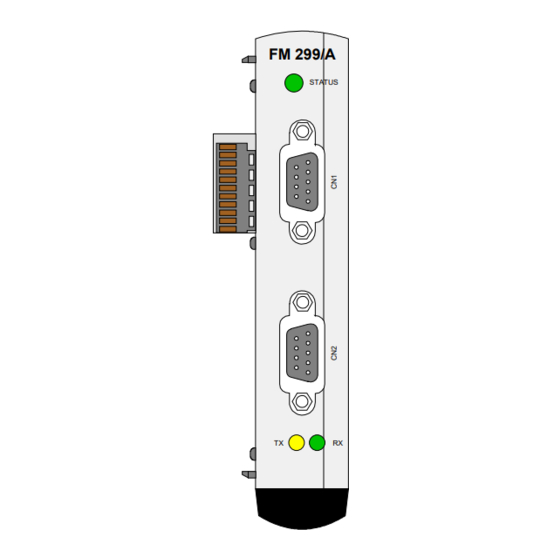
SANMOTION C FM 299/A GA1060 Field bus master module
Brand:
Keba
| Category:
Control Unit
| Size: 0.15 MB
Table of Contents
Table of Contents
5
1 Brief Description
7
2 General Safety Instructions
8
3 Configuration
9
Configuration with the Kemro.manager
9
Creation of Cfg-File
10
Setting the K-Bus Address
11
4 Connections, Wiring
12
SDC Bus Interface
12
General Information
12
Connector
12
Cable
12
Cable Routing
13
Bus Topology
13
Schematic Diagram of the Bus Topology Bus Terminating Board
14
5 Operation and Displays
15
Status LED
15
GA1060 Bus Status Leds
15
6 Technical Data
16
Advertisement
Related Products
Keba Kemro NX 252/A
Keba Kemro TM 225/A
Keba Kemro FX 271/A
Keba Kemro FX 271/B
Keba Kemro CP 263/S
Keba Kemro CP 263/X
Keba Kemro MM 240/A
Keba Kemro MM 280/A
Keba Kemro FM 280/A
Keba KeContact P30 c-series
Keba Categories
Battery Charger
Control Unit
Controller
Automobile Accessories
Measuring Instruments
More Keba Manuals
Login
Sign In
OR
Sign in with Facebook
Sign in with Google
Upload manual
Upload from disk
Upload from URL