Table of Contents
Advertisement
Advertisement
Table of Contents

Subscribe to Our Youtube Channel
Related Manuals for Regin Corrigo U10 Series


Summary of Contents for Regin Corrigo U10 Series
- Page 1 U10...20 User manual...
-
Page 2: Table Of Contents
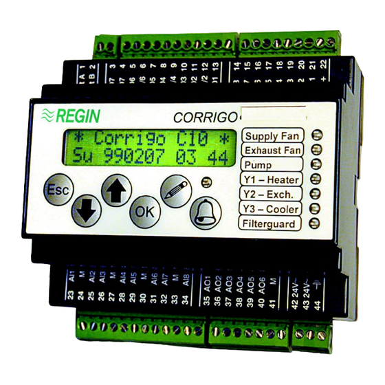
Introduction U-series is a completely new range of digital controllers designed for ORRIGO controlling of district heating sub-stations and boiler stations. The controllers have a display and built in panels for operation and alarm on the front and are operated by means of clearly defined buttons. -
Page 3: Model Overview U10 - U20
Overview - models for heating control for heating control is available in two models which differ slightly in their ORRIGO control function and in the number of inputs and outputs. Both models are available without, U10 and U20 or with, U10-LON and U20-LON communication via LON Works. -
Page 4: Overview U10
- U10 ORRIGO Overview 6 analogue sensor inputs Pt1000 4 digital inputs 3 analogue outputs 0...10 V 4 digital outputs The controller has outdoor temperature dependant heating control of one radiator system HS1 using one control valve (HS1-CV1). Also control of tap hot-water using either one or two separate control circuts HW and THW or a single control circuit with two sequences THW-CV1 and THW-CV2. -
Page 5: Overview U20
- U20 ORRIGO 8 analogue sensor inputs Pt1000 5 digital inputs 6 analogue outputs 0...10 V 7 digital outputs The controller has outdoor temperature dependant heating control of two radiator systems HS1and HS2 using for each one or two control valves (HS1-CV1, HS1-CV2 and HS2-CV1, HS2-CV2). Also control of tap hot-water using either one or two separate control circuts HW and THW or a single control circuit with two sequences THW-CV1 and THW-CV2. -
Page 6: Installation
Installation can be mounted in standard casing, on a DIN rail in a cabinet or in the front ORRIGO of a cabinet. Front mounting kit When C is to be placed in a cabinet front mounting will be facilitated using the ORRIGO front mounting kit FMK1. -
Page 7: Wiring Diagrams
Wiring diagram U10 Net A LON-connection U10-LON only Net B LON-connection U10-LON only DO7 Alarm output DO7 Alarm output 24 V AC/DC DO6 Not connected Not connected DO5 Not connected DO4 Not connected 24 V AC in DO3/DO4 24 V AC DO3 3p. - Page 8 Wiring diagram U20 Net A LON-connection U20-LON only Net B LON-connection U20-LON only DO7 Alarm output DO7 Alarm output 24 V AC/DC DO6 3p. outp. HS2-CV1 - decrease / TO1 24 V AC in DO5/DO6 DO5 3p. outp. HS2-CV1 - increase / TU2 DO4 Control Pump HS2-P 24 V AC in DO3/DO4 24 V AC...
-
Page 9: Description Inputs
Wiring AI Analogue inputs has analogue inputs AI for connecting temperature sensors. PT1000 type ORRIGO temperature sensors must be used. The function of some of the inputs varies depending on the choice of model and configuration. AI-inputs must always use the signal neutral of the AI terminal block as reference. (terminals 24, 27, 30 or 33). -
Page 10: Description Outputs
Wiring Digital inputs DI has digital inputs DI for activation of certain functions and input of external ORRIGO alarm signals. N.B. These inputs may only be wired to voltage-free contacts. Important These inputs may only refer to the common DI pole on terminal 22. Terminal 22 does not have the same potential as other signal neutrals in the C ORRIGO and may not be connected to any other terminals except the DI inputs. - Page 11 Wiring Digitala utgångar DO has 7 digital outputs DO1...DO7. ORRIGO DO7, alarm output is a voltage free closing relay contact. 1 A, 24 V AC/DC. DO6 ut The outputs DO1...DO6 are triac controlled, 0.5 A, 24 V AC. Short term 1 A. 24 V AC in The triac outputs are paired to common supply terminals for 24 V AC.
- Page 12 Buttons on the front Arrow up – move upwards in the menu. In the ”Change” position the button is used to INCREASE the value indicated. When the button is held in a depressed position the function is repeated. Arrow down – move downwards in the menu. In the ”Change” mode the button is used to DECREASE the value indicated.
- Page 13 Information series - rolling display *CORRIGO U20* VS1 Börv/Ärvärde VVBörv/Ärv/Utst Må 980907 10:10 25.0ºC / 25.0ºC 60°C/60°C/45% During normal running when the buttons are not in use a series of menu pages is shown. The display alternates between a general display with product description and clock, setpoint/actual temperature, output status for the control outputs Y1,Y2 and Y3 and setpoint, actual value and output status for supply air fan and exhaust air fan and sepoint and actual value for the humidity control.
-
Page 14: Alarm Handling - Alarm Queue
Menu information If the user attempts to make changes that cannot be made or which lie outside his user level the controller will display the following information: Unauthorised No changes in Make new logon this menu Menu help text There are extra help-text to most of the menu pages. By pressing the OK button (except when in ”Change mode”) the extra text will be displayed. - Page 15 3. Should the code for level three be lost the sys- tem can be opened by means of a code number which can be obtained from REGIN. This code number is time dependent. Manual C...
-
Page 16: Configuration
Configuration Configuration implies the commissioning setting of all the parameters in the C ORRIGO Parameters are set using script. Configuration codes There is also the option of setting parameters by means of two configuration codes. This function is particularly useful and time-saving when a number of controllers are to be configured in the same way. - Page 17 Configuration Some of the functions are not available on all models. This due to that some of the inputs or outputs have alternative functions. A. Function sensor AI1 Outdoor sensor. Fixed setting. Do not change Since the heating control is outdoor temperature dependant this sensor must be installed and configured for correct function.
- Page 18 G. Function sensor AI7 (C U20 only) ORRIGO Input not active HS2 Supply. Must be configured as HS2 Supply if the sequence HS2is to be used for heating control. Function as for AI2, see point B. H. Function sensor AI8 (C U20 only) ORRIGO Input not active...
- Page 19 O. HS2-CV1 typ (C U20 only) ORRIGO 0...10V DC Controls the actuator using an analogue 0...10 V DC signal on output AO1. Control parameters are set in the menu ”Control HS2”. 3-point Controls the actuator using increase/decrease signals on the outputs DO5 and DO6.
-
Page 20: Control Hs1
Konfigurering, snabbmetod At the top of the configuration branch there are two menues, Configuration code 1 and Configuration code 2. Each position in the code corresponds, in order, to hte menues A to V described on the previous pages. The codes may be set directly in these two menues. Tables for configuration code There is also a special table to facilitate the choice of configuration code. -
Page 21: Control Hs2
15 P-Band / I-Time 16 Running time HS1-CV1 Only shown if HS1-CV1 is configures as 3-point. Control HS2 U20 only ORRIGO Identical to Control HS1 but for HS2 Control HW/THW In this menu branch you can look at and set most control values for the control of the HW and THW circuits. -
Page 22: Outputs
AO Analogue out In this menu branch you can look at the configuration and output of the analogue outputs. AO1 Control valve for heating sequence 1, HS1-CV1. Only shown if HS1-CV1-type is configured as 0...10 V DC (See Configuration point K) AO2 Control valve HW-CV1 if THW is configured as 1 sequence or Control valve THW-CV1 if THW is configured as 2 sequences. -
Page 23: Scheduler
Scheduler The C has a year-base clock. This means that a week-schedule, individual ORRIGO holidays and holiday periods for a full year can be set. The clock has at least 24 hours running reserve. Clock Can be changed from userlevel 1 and up. Time In this menu you can set date and time. -
Page 24: Alarm Settings And Alarm Queue
Alarm settings Here all settings for the alarm system are set including alarm parameters, delays, suppression times etc. Temperature deviation alarm HS1 Temp.dev. alarm Should the actual temperature differ from the setpoint by more than the set 5.0K / 2 min value an alarm will be activated after a set time. -
Page 25: Settings (Other)
Settings This menu contains various settings that are normally only set at the comissioning of the C ORRIGO Which alternatives are shown depends on the model and the configuration settings. 1. K-factor HS1-Room Sets the ratio between a change in supply water temperature and the resulting change in room temperature. - Page 26 Factory settings U10 Configuration Factory setting Config.code 1 1100.1100.0000 Config.code 2 0000.0110.11 AI1 = Outdoor temperature AI2 = HS1 Outgoing water temperature AI3 = Not used AI4 = Not used AI5 = HW Outgoing water temperature AI6 = THW Outgoing water temperature AI7 = Not used in Corrigo U10 AI8 = Not used in Corrigo U10 HS1 No night setback...
-
Page 27: Configuration Table U10
Commissioning protocol U10 Installation System Commiss.date Commiss. by Page 1 Configuration Factory setting Commissioning setting Config. code 1 1100.1100.0000 ____._____._____ Config. code 2 0000.0110.11 ____._____.___ A. AI1 1 Outdoor temp _______________ B. AI2 1 HS1 Supply _______________ C. AI3 0 -------- _______________ D. - Page 28 Commissioning protocol U10 Installation System Commiss. date Commiss. by Page 2 Scheduler Factory setting Commiss. setting NRed 1 HS1 -------- 00:00-00:00 _______________ NRed 2 HS1 -------- 00:00-00:00 _______________ Standby HS1 -------- 00:00-00:00 _______________ Alarm settings 1. Control alarm HS1 5K / 5 min ______ / _______ 2.
-
Page 29: Configuration Table U20
Commissioning protocol U20 Installation System Commiss.date Commiss. by Page 1 Configuration Factory setting Commissioning setting Config. code 1 1100.1110.0000 ____._____._____ Config. code 2 0000.0111.11 ____._____.___ A. AI1 1 Outdoor temp _______________ B. AI2 1 HS1 Supply _______________ C. AI3 0 -------- _______________ D. - Page 30 Commissioning protocol U20 Installation System Commiss.date Commiss. by Page 2 Control HS2 Factory setting Commiss. setting Man. offset _______________ Setpoint room 20.0°C _______________ Nightreduction / Standby -1.0 / -2.0 _______ / ______ Outdoor plot 1 -20.0°C / 65.0°C _______ / ______ Outdoor plot 2 -10.0°C / 55.0°C _______ / ______...
-
Page 31: Index
CONFIGURATION- Corrigo U10 A B C D . E F G H . I J K L Configurationcode 1 A Function sensor AI1 1. Outdoor sensor (Do not change) B Function sensor AI2 0. --- Input not active 1. HS1 Outgoing C Function sensor AI3 0. - Page 32 CONFIGURATION- Corrigo U10 M N O P . Q R S T . U V Configuration code 2 0 0 0 0 . M Not available to Corrigo U10 0. Not active (Do not change) N Not available to Corrigo U10 0.
- Page 33 CONFIGURATION- Corrigo U20 A B C D . E F G H . I J K L Configurationcode 1 A Function sensor AI1 1. Outdoor sensor (Do not change) B Function sensor AI2 0. --- Input not active 1. HS1 Outgoing C Function sensor AI3 0.
- Page 34 CONFIGURATION- Corrigo U20 M N O P . Q R S T . U V Configuration code 2 M Night setback HS2 0. No 1. Yes N Room compensation HS2 0. No 1. Yes O HS2-CV1 type 0. 0...10 V DC 1.
- Page 35 Manual C 2002-09 ORRIGO SERIE...
- Page 36 Regin´s business mission is to be a flexible, global partner providing first-rate products for indoor climate control. Our products are designed for creating a pleasant indoor climate while, at the same time, utilizing energy in the most cost-effective way possible. The product range consists of Regin´s...
Need help?
Do you have a question about the Corrigo U10 Series and is the answer not in the manual?
Questions and answers