Advertisement
Available languages
Available languages
Quick Links
INSTRUCTION
EN
REGIO RC-DTO
i
Read this instruction before installation
and wiring of the product
Consult documentation in all cases where this symbol
is used, in order to find out the nature of the potential
hazards and any actions to be taken
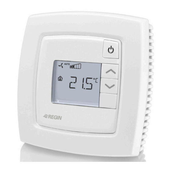
Room controller with display and two outputs
for valves with three-point actuators
RC-DTO is a room controller from the Regio Mini series, intended to
control heating and cooling in a zone control system. The controller
has four digital outputs for controlling two valves with three-point
actuators (increase-decrease), and a display. Installation is directly
on the wall or on an electrical connection box. The controller does not
have a communication connection.
Technical data
Supply voltage
18...30 V AC, 50...60 Hz
Internal consumption
2.5 VA
Ambient temperature
0...50°C
Ambient humidity
Max 90% RH
Storage temperature
-20...+70°C
Display
LCD with background illumination
Built-in temperature sensor NTC Type, range 0...50°C, accuracy
+/-0.5°C at 15...30°C
Inputs and outputs
Refer to connection illustrations and table
below
Connection terminals
Lift type for cable cross-section 2.1 mm
Protection class
IP20
Material, casing
Polycarbonate, PC
Weight
110 g
Dimensions
95 x 95 x 28 mm
Occupancy button
INCREASE button
DECREASE button
Installation
Place the controller in a location that has a temperature representative for
the room. A suitable location is approx. 1.6 m above floor level in a place
with unobstructed air circulation.
Remove the frame by depressing the locking tab in the lower edge of the
cover with a screwdriver. See figure 1.
Then prize out the electronics cassette using the four rectangular screwdri-
ver slots and levering against the edge of the bottom plate. See figure 2.
Note: Take care not to damage the electronics when inserting the screw-
driver into the slots.
Figure 1
Figure 2
The bottom plate with terminals has a number of fixing hole combina-
tions. Select suitable holes (see figure 3) and screw the bottom plate onto
the wall or connection box, so that the arrows on the bottom plate point
upwards. Do not tighten the screws too hard!
With surface-mounted cabling, break-out suitable holes from the marks in
the plastic.
RC-DTO
2
10 11 12 13 14
20 21 22 23 24
UP
60
30 31 32 33
40 41 42 43
Figure 3. Bottom plate with mounting alternatives and location of
terminals (dimensions in mm.)
°C
30
AI1
31
UI1
32
DI1
°C
33
DI2/CI
40
+C
41
AGnd
42
-
43
-
Figure 4. Connection diagram for RC-DTO
30
AI1
31
UI1
32
DI1
33
DI2/CI
40
+C
41
AGnd
42
-
Figure 5. Alternative connection for terminals 31, UI1, and terminal 33, DI2/CI
43
-
UP
68
G
10
24 V AC
G0
11
DO1
12
G0
G
DO2
13
DO3
14
GDO
20
G0
21
DO4
22
DO5
23
-
24
1
Advertisement

Related Manuals for Regin REGIO RC-DTO


Summary of Contents for Regin REGIO RC-DTO
- Page 1 INSTRUCTION Inputs and outputs Refer to connection illustrations and table REGIO RC-DTO below Connection terminals Lift type for cable cross-section 2.1 mm Protection class IP20 Material, casing Polycarbonate, PC Weight 110 g 10 11 12 13 14 20 21 22 23 24...
- Page 2 RC-DTO has an input for change-over that automatically resets the Ter- Desig- Operation DI2/CI Regin’s condensation detector, KG-A (FS). The output UO1 to operate with heating or cooling function. The input can minal nation sensor is connected between terminals 33 and 41,...
- Page 3 Setpoint Buttons Parameter number In Occupied mode, the controller operates from a heating setpoint RC-DTO has the following buttons: The following parameters can be changed in the parameter menu: (FS = 22°C), or a cooling setpoint (FS = 24°C) that can be changed •...
-
Page 4: Installation
Contact and heating is applied Mått 95 x 95 x 28 mm AB Regin, Box 116, 428 22 Kållered, Sweden 50-55 No function for this model Tel: +46 31 720 02 00, Fax: +46 31 720 02 50 Temperature compensation on AI1 0°C... - Page 5 Plocka därefter ur elektronikkassetten med hjälp av de fyra demonter- För trepunktsställdon värme minska. 24 V AC ut- °C ingshålen genom att bända mejseln mot kanten på bottenplattan. Se 24 V AC gång, max 0,5 A. Ställdonets plint för stängsignal figur 2.
- Page 6 Inställningar kylbörvärde + 3°C). Displayhantering Occupied: Rumstemperaturen regleras efter gällande kylbörvärde (FI = Värden som anges med FI kan ändras i parametermenyn i displayen. Indikeringar 24°C) eller värmebörvärde (FI = 22°C). Displayen har följande indikeringar: Bypass: Styrs av närvarodetektor eller annan digital kontakt ansluten till Reglerfall regulatorn, slutning aktiverar Bypass.
- Page 7 MINSKA-knappen. Reglerfall: 0=Värme, 1=Värme/Värme, Minflöde på kylutgången då reglerfall När rätt parameter är vald trycker man på Närvaroknappen. Värdet 2=Värme eller kyla via Change-over, värme/kyla med VAV-reglering är vald på parametern visas och parameternumret försvinner. Värdet på 3=Värme/Kyla, 4=Värme/Kyla med forcerad Maxflöde på...
- Page 8 3 points. Kontakt tournevis. AB Regin, Box 116, 428 22 Kållered RC-DTO est un régulateur d’ambiance de la gamme Regio Mini qui Tel: +46 31 720 02 00, Fax: +46 31 720 02 50 permet de réguler le chauffage et le refroidissement dans les systèmes www.regin.se, info@regin.se...
- Page 9 Pour diminuer le chauffage avec un actionneur 3 DI2/CI Détecteur de condensation de Regin, KG-A (RU). °C 24 V AC points. Sortie 24 V AC, max 0,5 A. La borne du Le détecteur est branché sur les bornes 33 et 41 signal de commande de la fermeture de l'action- (AGnd).
- Page 10 chauffage est actif. Si la batterie chaude n’est pas située sur la gaine Inoccupé (Unoccupied) : Ce mode est à utiliser pour des périodes d’ab- Gestion de l’affichage d’air neuf et si vous voulez éviter que le registre s’ouvre en fonction sence longue (par ex.
- Page 11 Réglage des paramètres Valeur de consigne refroidissement en mode 30 °C Durée de fonctionnement de l'actionneur de 120 s Changer un paramètre Inoccupé. refroidissement lorsqu'un actionneur ToR est Pour choisir et changer la valeur d’un paramètre, il faut utiliser le menu utilisé.
- Page 12 Contact 0 = NO (Normalement ouverte), Dieses Symbol macht auf eventuelle Gefahren bei der Regin Control SARL, 32 rue Delizy, 93500 Pantin 1 = NF (Normalement fermée) Handhabung des Produktes sowie auf in der Doku- Tél : 01 41 71 00 34, Fax : 01 41 71 46 46 Etat de l'entrée digitale 2 (DI2) :...
- Page 13 Funktion Siehe auch nachfolgenden Abschnitt Präsenz- nung melder. Versorgungsspannung 24 V AC DI2/CI Regin-Kondensationsfühler, KG-A (WE). Der 10 11 12 13 14 20 21 22 23 24 Fühler wird zwischen Klemmen 33 und 41 (AGnd) Versorgungsspannung 0 V angeschlossen. Für Zwangslüftung. 24 V AC-Ausgang, max. 0,5 A.
- Page 14 Alternativ kann ein potentialfreier Kontakt verwendet werden. Ist der Kon- Das Umschalten zwischen Heiz- und Kühlsollwert geschieht je nach 24 V DC Spannung, gemeinsam für DI und UI takt geöffnet, arbeitet der Regler mit der Heizfunktion. Bei geschlossenem Heiz- und Kühlbedarf im Regler automatisch. (auf digital gestellt) Kontakt ist die Kühlfunktion aktiv.
- Page 15 Wenn die Präsenztaste kürzer als 5 Sekunden gedrückt wird, Neutrale Zone bei Standby. 3 °C Wählen Sie, ob Sollwert oder Istwert im während der Regler ausgeschaltet oder im Standard-Betriebs- SW Heizen = Basis-SW Heizen - 3. Display angezeigt wird: 0 = Sollwert, 1 = modus ist, schaltet der Regler in den Betriebsmodus Bypass um.
- Page 16 3 = Im Display wird SW Kühlen+An- passung angezeigt. Dieses Produkt trägt das CE-Zeichen. Mehr Information können Sie auf www.regincontrols.de finden. Kontakt Regin Controls Deutschland GmbH Tel: +49 30 77 99 40, Fax: +49 30 77 99 479 www.regincontrols.de, info@regincontrols.de RC-DTO...
Need help?
Do you have a question about the REGIO RC-DTO and is the answer not in the manual?
Questions and answers