
Related Manuals for Regin RCF Series


Summary of Contents for Regin RCF Series
- Page 1 W E TAK E B U I L D I N G AU TO M AT I O N PER SO N A L LY MA NUAL © Copyright AB Regin, Sweden, 2016...
- Page 2 The information in this document is subject to change without prior notification. The software described in this document is supplied under licence by Regin and may be used or copied only in accordance with the terms of the licence. No part of this document may be reproduced or transmitted in any form or fashion, electronically or mechanically, without the express, written permission of Regin.
-
Page 3: Table Of Contents
Table of contents CHAPTER 1 ABOUT THIS MANUAL ..................5 Terms ..........................5 Additional information ..................... 5 CHAPTER 2 INTRODUCTION TO RCF ..................6 ......................6 FAN COIL CONTROLLERS ......................6 WITH COMMUNICATION CHAPTER 3 MODELS ......................8 Design ..........................9 CHAPTER 4 TECHNICAL DATA .................... - Page 4 ....................... 44 OIL STATUS REGISTER ........................45 NPUT REGISTER ........................46 OLDING REGISTER CHAPTER 18 BACNET SIGNAL TYPES .................. 51 CHAPTER 19 BACNET SIGNALS ..................52 ........................52 NALOGUE INPUTS ........................52 NALOGUE VALUES ........................53 INARY INPUTS ........................54 INARY VALUES .............................
-
Page 5: Chapter 1 About This Manual
Regio in EXO Projects – Information on how the RCF can be used in the EXO system. RCF may be used in the same way as Regio Midi in the EXO system. The information is available for download from Regin's website, www.regincontrols.com. RCF manual... -
Page 6: Chapter 2 Introduction To Rcf
Models of RCF that feature the letter “C” in their designation (e.g. RCF-230CTD) offer built-in communication. Controllers featuring communication can be connected to bus lines, such as Modbus, Regin’s bus system EXOline or BACnet, in order to communicate with a central SCADA system via RS485. - Page 7 Application examples RCF manual Chapter 2 Introduction to RCF...
-
Page 8: Chapter 3 Models
Chapter 3 Models The RCF line consists of 9 different models of room controllers. Models ● ● ● ● ● (●) RCF-230(C)TD ● ● ● ● RCFM-230TD ● ● (●) RCF-230(C)AD Valve ● ● ● (●) RCF-230(C)D ● ● ● RCFM-230D ●... -
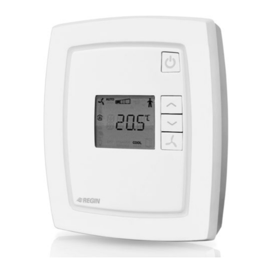
Page 9: Design
Design Figure 1. RCF-230X Figure 2. RCFM-230X RCF manual Chapter 3 Models... -
Page 10: Chapter 4 Technical Data
Chapter 4 Technical data Supply voltage ................230 V AC ±10 %, 50...60 Hz Power consumption ......................< 3 W Outputs, relays for fan control ....230 V AC, 3 A fan-coil (NA for RCF230-CTD-EC) Actuator, Triac .......... 230 V AC, max. 300 mA (NA for RCF230-(C)AD) ©... -
Page 11: Accessories For Rcf
External temperature sensor ....... TG-R5/PT1000, TG-UH/PT1000, TG-A1/PT1000 Presence detector ......................IR24-P Change-over ...................... TG-A1/PT1000 The accessories are available from Regin. For more detailed information concerning these accessories, see the individual product sheet and instruction for each product, available via www.regincontrols.com. -
Page 12: Chapter 5 Preparations For Installation
Chapter 5 Preparations for installation Using labels A series of labels are located on the back of the electronics cassette, which simplify extensive installations of RCF controllers. By using these labels to convey information to the individual responsible for the physical installation, it is possible to save much time and to minimise errors during wiring. -
Page 13: Configuration
Example 2 If the label address is 10:001, the following addresses are used for the different communication protocols: EXOline: PLA=10, ELA=1. Modbus: Address=1. BACnet: Device ID=10001 (the 4 low digits=1, the 3 high digits=1), MS/TP MAC address=1. Configuration © Regio tool is used in order to configure the electronic unit. -
Page 14: Chapter 6 Installation
Chapter 6 Installation Mounting Mount the controller in a location that has a temperature representative for the room. A suitable location is approx. 1.6 m above floor level in a place with unobstructed air circulation. Depress the locking tab in the top edge of the cover by using a screwdriver. Gently twist the screwdriver until the bottom plate and the electronic unit separate somewhat (see figure 3, below). -
Page 15: Bottom Plate Connections
Bottom plate connections Figure 6. Bottom plate connections RCF manual Chapter 6 Installation... -
Page 16: Wiring For Models Rcf(M)-230(C)Td
Wiring for models RCF(M)-230(C)TD Wiring of thermal actuator Wiring of electric heater with solid state-relay (RCF-230CTD) (RCF-230CTD) RCFM-230 TD can only be wired in this fashion Wiring of electric heater with PULSER-ADD Wiring of 3-position actuator (RCF-230CTD) (RCF-230CTD) Chapter 6 Installation RCF manual... -
Page 17: Wiring Of Various Actuators
Wiring of various actuators When wiring thermal actuators, DO4 is used for heating and DO5 for cooling actuators. If the change-over function is used together with a 2-pipe installation, the actuator should be connected to DO4 if an electric heater is not used. If an electric heater is used, the change- over function is instead located on DO5. -
Page 18: Wiring For Model Rcf-230Ctd-Ec
Wiring for model RCF-230CTD-EC Wiring diagram Wiring for change-over Wiring of electric heater Wiring of electric heater and PULSER-ADD Chapter 6 Installation RCF manual... - Page 19 Terminal Designation Description Function 230 V AC Line Supply voltage Not connected 230 V AC Neutral Power supply (internally connected to terminal 13) Fan-coil common / 230 V Common fan-coil connector AC Neutral (internally connected to terminal Not connected Digital output 4 for Digital output, 230 V AC, max 300 heating/cooling or opening mA (3 A initially)
-
Page 20: Wiring For Models Rcf-230(C)Ad
Wiring for models RCF-230(C)AD Wiring of 0...10 V actuator (RCF-230CAD) Terminal Designation Description Function 230 V AC Line Supply voltage Not connected 230 V AC Neutral Power supply (internally connected to terminal 13) Fan-coil common / 230 V Common fan-coil connector AC Neutral (internally connected to terminal 12) -
Page 21: Wiring For Modelsrcf(M)-230(C)D
Terminal Designation Description Function Analogue input For external room sensors or supply air temperature limitation sensor, PT1000. Measuring range 0...50°C. The sensor is connected between terminals 42 and 44, AGnd. Universal input Potential-free window contact or dito change-over input (configurable for NO/NC) or analogue PT1000 sensor. - Page 22 Terminal Designation Description Function 230 V AC Line Supply voltage Not connected 230 V AC Neutral Power supply (internally connected to terminal 13) Fan-coil common / 230 V Common fan-coil connector AC Neutral (internally connected to terminal Fan-coil output 1 for fan Relay, 230 V AC, 3 A control Fan-coil output 2 for fan...
-
Page 23: Chapter 7 Commissioning
Chapter 7 Commissioning © For models with communication, it is easiest to set parameters by using Regio tool If the measured room temperature is to be compensated for, this should be performed only under stable conditions. Troubleshooting © The Manual/Auto function in Regio tool enables testing various outputs. -
Page 24: Chapter 8 Control Principles
Chapter 8 Control principles RCF-230(C)TD, RCF-230CTD-EC, RCF-230(C)AD, RCFM-230TD Control principle for cooling function, 2-pipe installations During control of cooling, the output starts to increase when the temperature rises above the setpoint value. Control principle for heating function, 2-pipe installations During control of heating, the output starts to increase when the temperature falls below the setpoint value. -
Page 25: Rcf-230(C)D, Rcfm-230D
The above schematic drawings of the control principle show the corresponding requirement of the controller function. This requirement is recalculated by the controller to a value for the actuator output, depending on the selected output function. RCF-230(C)D, RCFM-230D Control principle at cooling function During control of cooling, the output is activated when the temperature rises above the setpoint by the set hysteresis (ΔT). - Page 26 Control principle at Heating/Cooling with electric heater and change-over on DO5 RCF-230CTD(-EC) has a function for pulse/pause control of electric heaters. This function is similar to the control of a thermal actuator. When using an electric heater, the fan will run for an additional 2 minutes after the heater has been shut down in order to cool it off.
- Page 27 Control mode Min limitation Max limitation Heating 24°C 35°C Cooling 12°C 24°C A room controller will then work together with a supply air temperature controller using cascade control, resulting in a calculated supply air temperature maintaining the room temperature setpoint. The cascade factor consists of the supply air controller being faster than the room controller.
-
Page 28: Chapter 9 Operating Modes
Chapter 9 Operating modes Different operating modes There are four different operating modes. Switching between these modes is performed locally. In controllers with communication, the operating mode can also be changed through the main SCADA system. Comfort is shown in the display. A presence detector can be connected to DI in order to choose between Comfort and Economy. -
Page 29: Chapter 10 Button Management
Chapter 10 Button management On/Off button Fan speed Increase setpoint Increase setpoint displacement displacement Decrease setpoint Decrease setpoint displacement displacement Fan speed Manual change-over On/Off button By pressing the On/Off button, RCF will switch between Off mode and Comfort/Economy mode. Setpoint buttons The INCREASE and DECREASE buttons are used to change the setpoint displacement. - Page 30 Configuration via the parameter list The factory settings are changed in the parameter list shown in the display by using the buttons on the controller. The parameter values are changed with the INCREASE and DECREASE buttons and changes confirmed with the On/Off button. Setpoint displacement In parameter 34 and 35 it is possible to set the maximum permitted increase as well as decrease of the setpoint displacement.
-
Page 31: Chapter 11 Types Of Actuators
Chapter 11 Types of actuators RCF can be used with four types of actuators: • Analogue 0…10 V DC actuators • Thermal actuators • 3-point actuators (Increase/decrease actuators) • On/Off actuators (thermostat function) © The type of actuator is configured using Regio tool or in the parameter menu of the display. -
Page 32: Chapter 12 Fan Control
Chapter 12 Fan control Automatic fan speed control for RCF-230(C)TD, RCF- 230CTD-EC, RCF-230(C)AD and RCFM-230TD The current fan speed is shown in the display and can be set manually to Low, Medium or High speed. It can also be set to Auto, which means that the fan speed is controlled by the heating and/or cooling demand, depending on the configuration. - Page 33 Number of Factory Description parameter setting Configuration of fan control: 0=No control, 1=The fan is controlled by heating requirement, 2=The fan is controlled by cooling requirement, 3=The fan is controlled by both heating and cooling requirement. When using an electric heater this parameter should only be set to 1 or 3, otherwise there is a risk of overheating.
-
Page 34: Chapter 13 Change-Over
Chapter 13 Change-over Change-over is a function enabling installations using only 2-pipe systems to use the same pipe for both heating and cooling depending on whether heating or cooling is required during, for instance, the summer months (Cooling control) or winter months (Heating control). -
Page 35: Chapter 14 Display Handling
Chapter 14 Display handling The display is handled using the buttons on the controller: See chapter 10 for more information. Display indications Current fan speed (Low, Medium, High) Auto/Man. indication for the fan Adjustable value Occupancy indication Setpoint Room temperature Current room temperature or setpoint in °C to one decimal point Off mode (only... - Page 36 Return After approx. 1 minute, or when INCREASE and DECREASE is pressed simultaneously while in the menu, the display will return to its normal view mode. The text Exit is shown after the last parameter in the display. Pressing the On/Off button (or, in case of the RCFM, the Fan button) when Exit is shown will eject the user from the parameter menu.
- Page 37 Number of Factory Description parameter setting (FS) Output signal for actuator connected to AO2: 0=0…10 V 1=2…10 V 2=10…2 V 3=10…0 V Period time for heating actuator if thermal 60 s actuators. Period time for cooling actuator if thermal 60 s actuators.
- Page 38 Number of Factory Description parameter setting (FS) Manual/Auto heating output signal: 0=Off 1=Manual 2=Auto Manual/Auto cooling output signal: 0=Off 1=Manual 2=Auto Heating output signal in manual mode. Cooling output signal in manual mode. Model. Major version. Branch version. Launched version or beta version. Revision.
- Page 39 Number of Factory Description parameter setting (FS) Setting, active buttons RCF: 0 = No active buttons 1 = Only On/Off button active 2 = Only Up/Down buttons active 3 = On/Off and Up/Down buttons active 4 = Only fan button active 5 = On/Off and fan button active 6 = Up/Down and fan button active 7 = All buttons active...
-
Page 40: Chapter 15 Memory Functions During Power Failure
Chapter 15 Memory functions during power failure During a power failure, the controller has an integrated function that enables settings and configuration to be stored in a so-called non-volatile memory (EEPROM). Settings and configurations are saved in the memory whenever they are changed, so that the latest values are always stored. -
Page 41: Chapter 16 Modbus Signal Types
Chapter 16 Modbus signal types EXOL types EXOL signal types: R = Floating point number (Real) (-3.3E38 - 3.3E38) I = Whole number (Integer) (-32768 - 32767) X = Index (0 - 255) L = Logic (Logic) (0/1) Modbus types Modbus signal types (types listed below): 1 = Coil Status Register (Modbus function = 1, 5 and 15) 2 = Discrete Input (Modbus function = 2) - Page 42 RS422 is a full duplex communication, meaning that 4 connecting wires are required; 2 for sending (Tx+ and Tx-) and 2 for receiving (Rx+ and Rx-). Tx is used for sending and Rx for receiving, meaning the Tx in a unit must be connected to the Rx in another and vice versa. Pertaining to signal levels, etc., RS422 and RS485 are identical.
-
Page 43: Chapter 17 Modbus Signals
Chapter 17 Modbus signals Discrete inputs Modbus Name of signal Type Description address RC_Actual_L.RegioDigIn(0) Not used RC_Actual_L.RegioDigIn1 Value on digital input 1 Not used in this model RC_Actual_L.RegioUDigIn1 Value on universal digital input 1 RC_Actual_L.RegioDigOut(0) Not used RC_Actual_L.RegioDigOut1 Value on digital output 1 RC_Actual_L.RegioDigOut2 Value on digital output 2 RC_Actual_L.RegioDigOut3... -
Page 44: Coil Status Register
Coil status register Modbus Default Name of signal Type Description address value Not used in this model RC_Setp_L.RegioShutDown Puts the unit in Shutdown mode. RC_Setp_L.RegioFireAlarmStop Places the unit in Shutdown mode and prevents it from being activated again, unless this value is first set to “0”. RC_Setp_L.RegioDiNC(0) Not used RC_Setp_L.RegioDi1NC... -
Page 45: Input Register
Input register Modbus Name of signal Type Description address RC_Actual_X.RegioSoftware Type of Regio software: 0 = RCP 1 = RC RC_Actual_X.RegioVerMajor Major version RC_Actual_X.RegioVerMinor Minor version RC_Actual_X.RegioVerBranch Branch version RC_Actual_X.RegioRevision Revision Not used in this model RC_Actual_X.RegioUnitState Current running mode: 0 = Off 1 = Economy/Standby 2 = Not used... -
Page 46: Holding Register
Holding register Modbus Default Name of signal Type Description address setting Not used in this model RC_Setp_X.RegioHeatOutputSelect Manual/Auto heating output RC_Setp_X.RegioCoolOutputSelect Manual/Auto cooling output RC_Setp_X.RegioFanSelect Select fan mode: 0 = Off 1 = Manual speed 1 2 = Manual speed 2 3 = Manual speed 3 4 = Auto RC_Setp_X. - Page 47 Modbus Default Name of signal Type Description address setting RC_Setp_X.RegioControllerMode RCFM- Control mode selection: 230Cxx = 2 2= Heating or Cooling via change-over RCF- 3 = Heating/Cooling 230Cxx = 3 4 = Electric heating RC_Setp_X.RegioCVHeatType Type of actuator, heating: 0 = 0…10 V 1 = 2…10 V 2 = 10…2 V 3 = 10…0 V...
- Page 48 Modbus Default Name of signal Type Description address setting RC_Setp_X.RegioUo2 RCF- Signal connected on UO2: 230CAD = 4 0 = Not used 1 = Not used All others = 2 = Thermo valve, Cooling (not (C)AD) 3 = Not used 4 = Analogue valve Cooling (only (C)AD) RC_Setp_X.RegioModbusSlaveAddr...
- Page 49 Modbus Default Name of signal Type Description address setting RC_Setp_R.RegioUnOccSetPHeat 15°C Heating setpoint when in Unoccupied mode RC_Setp_R.RegioUnOccSetPCool 30°C Cooling setpoint when in Unoccupied mode RC_Setp_R.RegioFrostSetP Not used RC_Setp_R.RegioSetpointOffsetPos 13°C Max. upward setpoint displacement RC_Setp_R.RegioSetpointOffsetNeg 17°C Max. downward setpoint displacement RC_Setp_R.RegioSetPOffset Setpoint displacement RC_Setp_R.RegioPIDPGain...
- Page 50 Modbus Default Name of signal Type Description address setting RC_SetpExt_R.RegioMaxECFanSpeed 10 V Maximum speed of the EC fan RC_SetpExt_R.RegioRCFSetPoint 22°C Basic setpoint RC_Setp_R.SupplyAirTLim_HeatHi R, 3 Supply air max limitation for 35°C cascade control and heating control RC_Setp_R.SupplyAirTLim_HeatLo R, 3 24°C Supply air min limitation for cascade control and heating control...
-
Page 51: Chapter 18 Bacnet Signal Types
Chapter 18 BACnet signal types © BACnet In order to communicate via BACnet, the protocol has to be changed either via Regio tool or via the parameter list in the display. Once the protocol has been set to BACnet, it can only be switched back to EXOline and Modbus via the display. -
Page 52: Chapter 19 Bacnet Signals
Chapter 19 BACnet signals Analogue inputs Object name Object ID Description Unit Writeable RC_Actual_R.RegioRoomTemp Analog input, 0 Room temperature °C RC_Actual_R.RegioAIChangeOver Analog input, 1 Change-over temperature °C RC_Actual_R.RegioAnaIn1 Analog input, 2 Value on analogue input 1 °C RC_Actual_R.RegioUAnaIn1 Analog input, 3 Value on universal analogue input 1 RC_Actual_R.RegioSupplyAirTemp... -
Page 53: Binary Inputs
Object name Object ID Description Unit Writeable RC_Setp_R.RegioRoomTempRemote Analog value, 15 Remote control of room °C temperature. RC_Setp_R.RegioStandbySetPDeadBan Analog value, 16 Deadband for Standby mode °C Not used in this model Analog value, 17-26 RC_Setp_R.RegioMinECFanSpeed Analog value, 27 Lowest possible speed for the EC fan RC_Setp_R.RegioMaxFanSpeed Analog value, 28... -
Page 54: Binary Values
Binary values Object name Object ID Description Values Writeable Not used in this model Binary value, 0 RC_Actual_L.RegioCVHeatPulsProp Binary value, 1 Indicates pulse prop. heating ACTIVE/ INACTIVE RC_Actual_L.RegioCVCoolPulsProp Binary value, 2 Indicates pulse prop. cooling ACTIVE/ INACTIVE RC_Actual_L.RegioCVHeatInc Binary value, 3 Indicates heating increase ACTIVE/ INACTIVE... -
Page 55: Multistate Inputs
Multistate inputs Object name Object ID Description Values Writeable Not used in this model Multistate input, 0 RC_Actual_X.RegioUnitState Multistate input, 1 Current running 1=Off mode 2=Economy/Standby 3=Not used 4=Not used 5=Comfort RC_Actual_X.RegioControllerState Multistate input, 2 Current control 1=Off mode 2=Heating 3=Cooling RC_Actual_X.RegioFanSpeed Multistate input, 3... -
Page 56: Device
Object name Object ID Description Values Writeable RC_Non_Modbus.RegioButtonActiv Multistate value, 6 Buttons active 1=No buttons eConf 2=Occupancy button only 3=INCREASE/DECR EASE only 4=Occupancy button INCREASE/DECREA 5=Fan button only 6=Occupancy button and fan button 7=INCREASE/DECR EASE and fan button 8=All buttons Device The Device object contains to writeable properties;... - Page 57 Index 3-position actuators, 31 INCREASE/DECREASE buttons, 29, 35 Input register, 45 Inputs Analogue, 52 About this manual Binary, 53 Additional information, 5 Discrete, 43 Terms, 5 Multistate, 55 Additional information, 5 Installation, 14 Analogue actuators, 31 Introduction to RCF, 6 Analogue values, 52 Application examples, 7 Automatic control, 32...
- Page 58 Thermal actuators, 31 Troubleshooting, 23 Wiring Types of actuators, 31 communication, 14 3-position actuators, 31 Wiring for model RCF-230CTD-EC, 18 Analogue actuators, 31 Wiring for models RCF(M)-230(C)D, 21 Excercising, 31 Wiring for models RCF(M)-230(C)TD, 16 Exercising, 31 Wiring for models RCF-230(C)AD, 20 Thermal actuators, 31 Using labels, 12...
- Page 59 C H A L L E N G E R B U I L D I N G A U T O M A T I O N AB Regin Head office Box 116, S-428 22 Kållered, Phone: +46 31 720 02 00 info@regin.se...
Need help?
Do you have a question about the RCF Series and is the answer not in the manual?
Questions and answers