
Subscribe to Our Youtube Channel
Related Manuals for Sulzer ABS RW 400


Summary of Contents for Sulzer ABS RW 400
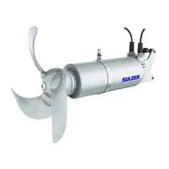
- Page 1 Submersible Mixer Type ABS RW 400 and 650 [NG] Submersible Recirculation Pump Type ABS RCP 400 and 500 [NG] Installation and Operating Instructions www.sulzer.com...
-
Page 2: Table Of Contents
1.7.3 Flange dimension check ........................12 Nameplate ............................. 13 Safety ..............................14 Transport and storage ........................14 Transport ............................... 14 Transport securing devices ........................14 3.2.1 Motor connection cable moisture protection ..................14 Storage of the units ..........................15 Sulzer reserves the right to alter specifications due to technical developments ! - Page 3 Bracket alignment on guide rail ......................26 Guide tube lengths RW (square tube) ....................26 Installation RCP ............................ 27 5.6.1 Installation example with Sulzer lifting unit .................... 27 5.6.2 Guide tube installation ........................... 28 5.6.3 Securing and positioning of the motor connection cables of the RCP ..........29 5.6.4...
-
Page 4: General
In case of doubt the entire scope of the planned application must be approved by Sulzer Pump Solutions Ireland Ltd. (in the following called Sulzer). In the case of any faults arising, Sulzer units should immediately be taken out of use and secured. The fault should be immediately rectified, or if necessary, contact your Sulzer Service Centre. -
Page 5: Application Areas
50 Hz or 60 Hz as indicated on the nameplate. In the event that the pump is to be operated in explosive atmospheres using a variable speed drive, please contact your local Sulzer representative for technical advice regarding the various approvals and standards concerning thermal overload protection. -
Page 6: Application Areas Rcp
1.4.2 Application areas RCP The ABS submersible recirculation pumps RCP 400 and 500 are fitted with water-pressure-tight encapsulated motors and are quality products suitable for use in the following areas: • Pumping and recirculation of active sludge in treatment plants with nitrogen removal (nitrification/denitrifica- tion). • Pumping of rain and surface water. 1.5 Identification code Hydraulics Motor AA BB C D U VVV / W-XY Ex EC;... -
Page 7: Technical Data Rw 50 Hz
1.6.1 Technical data RW 50 Hz Propeller Motor (50 Hz/400 V) Installation [mm] [1/min] [kW] [kW] [kg] [kg] RW 4021 ○ A 30/8 ● ● ● ● ○ RW 4022 ○ A 30/8 ● ● ● ● ○ RW 4023 ○... -
Page 8: Technical Data Rw 60 Hz
1.6.2 Technical data RW 60 Hz Propeller Motor (60 Hz/460 V) Installation [mm] [1/min] [kW] [kW] [kg] [kg] RW 4021 ○ A 35/8 ● ● ● ○ ● ○ RW 4022 ○ A 35/8 ● ● ● ○ ● ○ RW 4023 ○... -
Page 9: Technical Data Rcp 50 Hz
1.6.3 Technical data RCP 50 Hz Propeller Motor (50 Hz/400 V) [mm] [1/min] [l/s] [kW] [kW] [kg] RCP 4022 1.13 A 40/8 ● 10.9 ● ● ● RCP 4023 1.35 A 40/8 ● 10.9 ● ● ● RCP 4024 1.49 A 40/8 ●... -
Page 10: Dimensions And Weights
Dimensions and weights NOTE The weights of the units can be obtained from the nameplate of the unit or from the table in section 1.6 Technical data. 1.7.1 Dimensions RW Dimension ø 400 ø 650 ø 650 ø 650 ø 560 ø... -
Page 11: Dimensions Rcp
1.7.2 Dimensions RCP 188,5 2“ EN 10255-M X = PN6 Type 11, DIN EN 1092-1 Figure 2. RCP 400 2“ EN 10255-M (A50/12) 1005 (A75/12, A90/12, A100/12, A120/12) X = PN6 Type 11, DIN EN 1092-1 Figure 3. RCP 500... -
Page 12: Flange Dimension Check
1.7.3 Flange dimension check dimension “Y” (mm) +0.5 +0.5 (inch) 16" 1.44 +0.016 20" 1.69 +0.022 ange PN6 DIN EN1092-1 Typ 11 ange Class125 ANSI B16.1-2010 Figure 4. Flange dimensions ATTENTION Before installing the recirculation pump, check the “Y” dimension of the flange. Make sure that the dimensions specified in the table are adhered to, otherwise the flange will need to be reworked. -
Page 13: Nameplate
Weight Ø Prop Max amb Temp Continuous operating mode ≤ 70 dB Number of phases Frequency Sulzer Pump Solutions Ireland Ltd. Power (consumption) Wexford, Ireland. Insul. Cl.H Insulation class www.sulzer.com Rotation speed Power (output) Figure 5. Nameplate 50 Hz Weight Ø... -
Page 14: Safety
Safety The general and specific health and safety instructions are described in detail in the separate booklet Safety Instructions for Sulzer Products Type ABS. If anything is not clear or you have any questions as to safety make certain to contact the manufacturer Sulzer. Transport and storage Transport The unit must never be raised by the power cable. -
Page 15: Storage Of The Units
Storage of the units ATTENTION Sulzer products must be protected from weather influences such as UV from direct sunlight, high humidity, aggressive dust emissions, mechanical damage, frost etc. Sulzer original packaging with the relevant transport securing devices (where used) ensures optimum protection of the unit. If the units are exposed to temperatures under 0 °C / 32 °F check that there is no water in the hydraulics, cooling system,... -
Page 16: Structural Design
Structural design 4.2.1 RW 400 and 650 Figure 7. RW 400/650 Legend Bracket Mechanical seal Cable inlet Propeller boss Connection chamber Propeller Sealing of the motor chamber Shaft unit with rotor and bearings Stator SD ring Bracket with shackle Stainless steel covering (option) -
Page 17: Rcp 400 And 500
4.2.2 RCP 400 and 500 Figure 8. RCP 400/500 Legend Bracket Mechanical seal Cable inlet Propeller boss Connection chamber Propeller Sealing of the motor chamber Shaft unit with rotor and bearings Stator SD ring Lifting hook DI-electrode (seal monitor) Inlet cone... -
Page 18: Operation With Frequency Inverters
Operation with frequency inverters The stator design and the insulation grade of the motors from Sulzer means that they are suitable for usage with frequency inverters. It is however essential that the following conditions are met: • The guidelines for EMC (electromagnetic compatibility) are complied with. -
Page 19: Installation
The electrical connection is carried out in accordance with section 5.7 Electrical connection. NOTE We recommend that Sulzer installation accessories be used for the installation of the RW / RCP. Tightening torque... -
Page 20: Installation Examples Rw
Installation examples RW 5.3.1 Installation example with existing accessories We recommend that the closed bracket be used for this type of installation (See Figure 17). Figure 11. Installation example with exising accessories Legend Hoist with winch and rope Safety stop clamp Upper bracket with locking plate Swivelling square guide tube Closed bracket... -
Page 21: Installation Example With Alternative Fixing Possibilities
5.3.2 Installation example with alternative fixing possibilities We recommend that the open bracket be used for this type of installation (See Figure 17). Figure 12. Installation example with alternative fixing possibilities Legend Transportable lifting unit Swivelling wall mounted bracket Swivel handle Open bracket Socket (fixed installed) Cable clamp with cable hook Swivelling square guide tube Rope block... -
Page 22: Installation Example With Fixed Installation As Flow Booster
We recommend that the open bracket be used for this type of installation (See Figure 17). Figure 13. Installation example with fixed installation as flow booster Legend Rope block Tube retainer Cable clamp with cable hook Sulzer lifting unit 5 kN Square guide tube Open bracket Vibration damper Tube connector Bottom plate... -
Page 23: Fixed Installation With Vibration Damper
5.3.4 Fixed installation with vibration damper If the mixer is to be installed at a fixed point in the tank, then we recommend that the console with the vibration damper be used. In this case a further square tube must be used as a console at the guide tube. The vibration damper for the relevant mixer can be ordered (see table below). Vibration damper listing Mixer Part no. -
Page 24: Fitting Of The Open Bracket With Vertical Swivelling (Option)
5.4.1 Fitting of the open bracket with vertical swivelling (option) 8 (2x) 9 (2x) 5 (2x) 4 (2x) 10 (2x) 2 (2x) 13 (2x) VKT 60 (2x) 7 (2x) 12 (2x) 10 (2x) 8 (2x) 9 (2x) 5 (2x) 4 (2x) 10 (2x) 9 (2x) 10 (2x) - Page 25 5.4.2 Fitting of the closed bracket with vertical swivelling (option) 2 (2x) 5 (2x) VKT 60 (2x) 11 (2x) 5 (2x) 4 (2x) 3 (2x) 4 (2x) 9 (2x) 8 (2x) 6 (2x) 5 (2x) VKT 100 10 (2x) 11 (2x) 8 (2x) 9 (2x) Figure 17.
-
Page 26: Bracket Alignment On Guide Rail
5.4.3 Bracket alignment on guide rail The mixer must be set up freely suspended with bracket fully mounted so that the bracket points vertically towards the ground. When doing this the clamp of the mixer should be moved until the desired slope of the mixer is achieved. This ensures that the mixer can slide up and down easily on the guide tube after it is fitted. -
Page 27: Installation Rcp
Installation RCP 5.6.1 Installation example with Sulzer lifting unit Figure 19. Installation example with Sulzer lifting unit 5 kN... -
Page 28: Guide Tube Installation
5.6.2 Guide tube installation The safety hints in the previous sections must be observed! ATTENTION The discharge line and the required flange DIN EN 1092-1 PN6 should be installed on site before starting the installation of the guide tube. The DIN flange should be installed so that none of the holes in the flange are on the axis line but are symmetrically on either side of it. -
Page 29: Securing And Positioning Of The Motor Connection Cables Of The Rcp
5.6.3 Securing and positioning of the motor connection cables of the RCP The safety hints in the previous sections must be observed! NOTE The cable holders described here are not supplied as part of the standard execution of the RCP. Figure 21. Securing and positioning of the motor connection cables of the RCP •... -
Page 30: Lowering Of The Rcp Along The Guide Tube
5.6.4 Lowering of the RCP along the guide tube The safety hints in the previous sections must be observed! The RCP together with the guide piece is connected onto the guide tube and lowered along it until it automatically sits in it‘s final position (see Figure 23). When doing this, carefully feed the power cable downwards at the same time. To ensure the RCP will tilt enough to lower correctly on the guide tube, the angle of the pump created by the lifting hook when suspended by the hoist has to be checked prior to lowering. -
Page 31: Electrical Connection
Figure 23. RCP lowering RCP connected Electrical connection The safety instructions in the previous sections must be observed! Before commissioning, an expert should check that one of the necessary electrical protective devices is available. Earthing, neutral, earth leakage circuit breakers, etc. must comply with the regulations of the local electricity supply authority, and a qualified person should check that these are in perfect order. -
Page 32: Standard Connection Diagrams. Mains Voltage 380 - 420 V At 50 Hz / 460 V At 60 Hz
ATTENTION The only method of starting allowed is that specified in chapter 1.6 Technical data or on the nameplate. If you want to use other starting methods please consult the manufacturer. In the case where a control panel is not supplied as standard the unit must only be operated with a motor protection switch with overload relay and thermal sensors connected. -
Page 33: Lead Designations
5.7.2 Lead designations Direct starting in star Join North America T1 (U1)* T2 (V1)* T3 (W1)* Sulzer factory U2, V2, W2 standard Direct starting in delta North America T1 (U1)* T2 (V1)* T3 (W1)* Sulzer factory U1; W2 V1; U2 W1; V2 standard... -
Page 34: Checking Direction Of Rotation
Testing and adjustment of soft starter: ATTENTION For the first test adjust the potentiometer in position C. For further information consult the installation and operating instructions of the soft start manufacturer. These are supplied with the unit. Test: • First test with potentiometer setting “C”. Setting: •... -
Page 35: Changing Direction Of Rotation
North America only) must be connected to an intrinsically safe electrical circuit in accordance with FM (Factory Mutual) 3650. ATTENTION The Sulzer DI module must be located outside of the hazardous location. ATTENTION If the DI seal monitor is activated the unit must be immediately taken out of service. -
Page 36: Commissioning
Connect terminal 3 to ground or housing of the RW/RCP Power Supply CA 461 Output Input Leakage Figure 30. Electronic amplifier with collective signalling Electronic amplifier for 50/60 Hz 110 - 230 V AC (CSA) (Part No.: 1 690 7010) 18 - 36 V DC (CSA) (Part No.: 1 690 7011) ATTENTION Maximum relay contact loading: 2 Ampere Commissioning... -
Page 37: Types Of Operation
Should, nevertheless, a malfunction occur, do not improvise but ask your Sulzer Customer Service Department for assistance. -
Page 38: Maintenance Rw/Rcp
(approx. every 3 months) for wear and corrosion. These parts should be replaced if required! The Sulzer Service Organisation would be pleased to advise you on any applications you may have and to assist you in solving your aerating problems. -
Page 39: Inspection And Maintenance Intervals
Lift the unit out of the tank and clean it. Lifting equipment like hoists, shackles, wire ropes and wire clamps etc. must undergo a visual examination at regular intervals for wear and corrosion. MEASURE: Worn or damaged parts should be replaced. Please contact your local Sulzer Service Centre. ACTIVITY: Inspection of the propeller and the SD ring (Solids-Deflection-Ring). - Page 40 For safety reasons we recommend that all screws are checked for their perfect positioning once a year. MEASURE: Tighten screws with correct tightening torques (see 5.1). Manufacturer: Sulzer Pump Solutions Ireland Ltd. Clonard Road, Wexford Ireland Year of production: Serial no.:...
- Page 41 Recurring checks (at least once a year) Date Remarks Operating Signature Repaired hours on/by...
- Page 42 Sulzer Pump Solutions Ireland Ltd. Clonard Road, Wexford, Ireland Tel. +353 53 91 63 200. www.sulzer.com...
Need help?
Do you have a question about the ABS RW 400 and is the answer not in the manual?
Questions and answers