Table of Contents
Advertisement
Advertisement
Table of Contents

Related Manuals for Emerson Copeland EazyCool ZXDI Series


Summary of Contents for Emerson Copeland EazyCool ZXDI Series
- Page 1 Application Guidelines Copeland EazyCool ™ Indoor Condensing Units ZXDI Range...
-
Page 2: Table Of Contents
2.12.2 How to unlock the keyboard ................16 2.13 Parameters level 1 – Required settings ................. 16 2.14 Digital operation ......................16 2.15 Reset to factory settings – Emerson "Hot Key" ............. 17 2.15.1 How to save factory settings or user settings ............ 17 C6.1.10/0118-0318/E... - Page 3 2.15.3 Location of the "Hot Key" plug connection on the XCM25D controller ....18 2.15.4 How to program a "Hot Key" from the controller (upload) ........18 2.15.5 How to program a controller using an Emerson "Hot Key" (download) ..... 18 2.16 Troubleshooting – Alarm history ..................19 2.17 Compressor motor protection ..................
- Page 4 Maintenance & repair ..................31 5.1 Replacing a compressor ....................31 5.2 Condenser fins ....................... 31 5.3 Electrical connections ....................31 5.4 Routine leak testing ....................... 32 5.5 Condenser fans & motors ....................32 Certification & approval ................. 32 Dismantling & disposal .................. 32 DISCLAIMER ......................
-
Page 6: About These Guidelines
Besides the support they provide, the instructions listed herein are also critical for the proper and safe functioning of the condensing units. Emerson will not guarantee the performance and reliability of the product if it is misused in regard of these guidelines. -
Page 7: General Instructions
General instructions WARNING System breakdown! Personal injuries! Never install a system in the field and leave it unattended when it has no charge, a holding charge, or with the service valves closed without electrically locking out the system. System breakdown! Personal injuries! Only approved refrigerants and refrigeration oils must be used. -
Page 8: Product Description
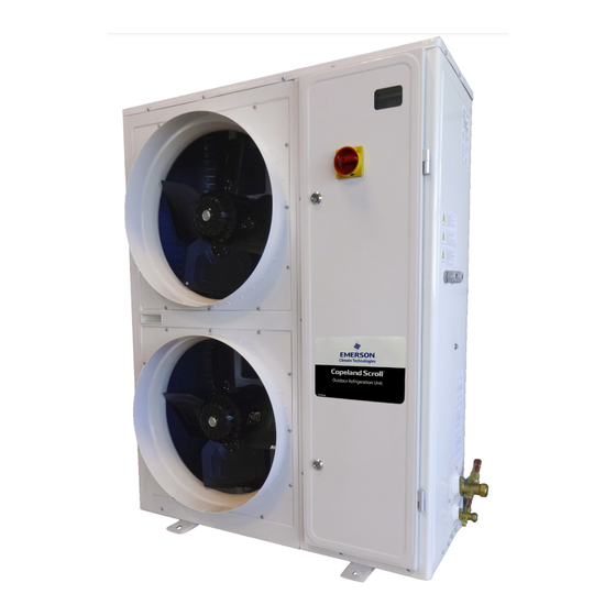
Common information about Copeland EazyCool™ ZXDI indoor condensing units Emerson has developed the Copeland EazyCool™ ZXDI indoor condensing unit to meet primarily the demands of the food retail and food service sectors. It is a refrigeration air-cooled condensing unit that uses the latest Copeland™ brand products patented Scroll technology as the main driver and has electronic protection and diagnostics features built in the compact chassis. -
Page 9: Application Range
Application Engineering representative. Bill of material Introduction Suction Family Controller concept date separator accumulator ZXDI Jan/2018 XCM25D (Emerson - Dixell) Table 2: BOM Main components description 2.8.1 Compressor Condensing Compressor model Compressor Compressor Unit rated unit (Digital) -
Page 10: Condenser Fan(S)
2.8.2 Condenser fan(s) WARNING Uncovered rotating parts! No safety grids on the condenser fans! Personal injuries! Never start the condensing unit or run the fans with no air ducts connected or without protective end-grids on the air outlets. The condensers of the ZXDI condensing units are equipped with single-phase fans. Maximum Power Fan blade... -
Page 11: Housing
2.8.3 Housing Copeland EazyCool ZXDI indoor condensing units have the following housing features: ▪ Controller-window in front of the cabinet door. The window is IP54 and shows the current value of the electronic controller. ▪ The main power switch is installed on the cabinet door and allows to de-energize the unit without opening the door. -
Page 12: P&I Diagram For Zxdi Units
P&I diagram for ZXDI units IMPORTANT Check valve in front of liquid receiver! Risk of excessive internal pressure caused by liquid expansion! Check required safety devices according to EN 378. Figure 5: P&I diagram for ZXDI units Fast access Position Description Comments menu... -
Page 13: Xcm25D Electronic Controller - Features
2.10 XCM25D Electronic controller – Features The XCM25D controller is designed to be a powerful, flexible controller for use in multiple applications. It has been developed for ZXDI condensing units and allows the adjustment of all relevant parameters by the user. 2.10.1 Description WARNING Electrical shock hazard! Serious personal injuries! There are unused fast-... -
Page 14: Main Control & Safety Features
Condenser fan Digital Scroll control control Alarm management Monitoring of the discharge Electrical line temperature protection Figure 7: XCM25D controller functionality overview 2.10.3 Main control & safety features Suction pressure control: Each unit is equipped with a suction pressure transmitter. The XCM25D controls the suction pressure by evaluating the input signal of the pressure transmitter. -
Page 15: Additional Features For Customization
Fixed high-pressure switches: This is a non-adjustable protection device designed to prevent the compressor from operating outside of its safe high-pressure range. Reset is automatic for a set number of trips (7) then the unit will lock out and require manual restart. This feature is important to prevent the unit from cycling under these controls for a long period of time. -
Page 16: Figure 8: Prearranged Additional Connections
Alarm contact Figure 8: Prearranged additional connections NOTE: Depending on the required functionalities additional components might be necessary. Please contact your local Application Engineering representative. NOTE: Check the current limitations given by the controller relays. NOTE: The solenoid valve function is not available on ZXDI indoor units. Digital output Specifications DO1, DO2 and DO3... -
Page 17: Xcm25D Electronic Controller - Programming
The unit will be turned on for the minimum run time when the low-pressure input is closed. If the pressure drops below the cut-out value or the low-pressure input opens, the unit should continue to run for the remaining minimum on time (C14/LAS) or until a satisfactory condenser pressure is reached (C13/LAd). -
Page 18: Remote Display Ccm60
There are two connection terminals on the back of the remote display (+ and -). NOTE: Emerson recommends using a shielded cable twisted pair 2 x 0.5mm². The device must be connected to the VNR-terminal on the unit controller according to the polarity. -
Page 19: Single Commands
Before connecting cables make sure the power supply complies with the hardware requirements. Separate the terminal cables from the power supply cables, the outputs and the power connections. 2.11.3 Single commands Press the SET button to display the target setpoint. In programming mode, this allows to select a parameter or to confirm an operation. -
Page 20: Entering Programming Level 2 "Pr2
2.11.6 Entering programming level 2 "Pr2" To enter the Pr2 programming menu: ▪ Press simultaneously for 3 seconds. The first parameter label will be displayed. ▪ Press till the T18 label is displayed, then press the key; ▪ The blinking PaS label will be displayed; wait for a few seconds; ▪... -
Page 21: How To Unlock The Keyboard
2.12.2 How to unlock the keyboard Keep the keys pressed simultaneously for more than 3 seconds, till the "Pon" message is displayed. 2.13 Parameters level 1 – Required settings The XCM25D is preconfigured to reduce the required settings on job-site to a minimum. In most cases it will not be necessary to enter programming level 2 "Pr2". -
Page 22: Reset To Factory Settings - Emerson "Hot Key
There is no way to reset the XCM25D controller to factory settings other than with additional equipment. Emerson recommends using the Emerson "Hot Key" (not part of the standard delivery) to save the factory settings at initial power up. The same hot key can also be used to save user settings. -
Page 23: Location Of The "Hot Key" Plug Connection On The Xcm25D Controller
NOTE: The "Err" message appears in case of a failed programming operation. In this case push the key again if you want to restart the upload or remove the "Hot Key" to abort the operation. 2.15.5 How to program a controller using an Emerson "Hot Key" (download) ▪ Turn the controller off. -
Page 24: Troubleshooting - Alarm History
2.16 Troubleshooting – Alarm history The controller records the total number of alarm activations (max 50) in the alarm menu (see Appendix 5). Action Key or display Notes Enter menu Push and release the ALR key. The menu to change the section will be entered. The Waiting for action alarm list section is active. -
Page 25: High Pressure: Pressure Relief Valve
2.18.4 Ambient temperature sensor An ambient temperature sensor supplied by Emerson is connected to the electronic controller. This temperature sensor has several functionalities like emergency mode control, lower fan speed limitation and crankcase heater control. -
Page 26: Dimensions In Mm
Figure 15: PKE-6 Fan speed controller details and dimensions NOTE: For more information about the fan speed controller and possible adjustments, please refer to the fan speed controller user’s guide – part of the unit standard delivery. 2.21 Dimensions in mm The figures hereafter show the overall physical dimensions of the ZXDI indoor condensing units: Figure 16: Dimensions of ZXDI condensing units (all models) C6.1.10/0118-0318/E... -
Page 27: Installation
Installation WARNING High pressure! Injury to skin and eyes possible! Be careful when opening connections on a pressurized item. Copeland EazyCool ZXDI indoor condensing units are delivered with a holding charge of neutral gas. The condensing unit should to be installed in a closed machine room. Soundproofing the machine room is highly recommended because of a potentially high sound production. -
Page 28: Electrical Connection
Electrical connection 3.2.1 Power supply connections Copeland EazyCool ZXDI indoor condensing units are designed for a 380-420V/3Ph/50 Hz power supply. A voltage tolerance of ± 10% is acceptable. The electrical connection of the condensing unit to the power supply must be made by qualified technicians according to the valid electrical directives, for instance DIN EN 60204-1. -
Page 29: Refrigeration Piping Connections
Overload setting Overload range Condensing unit Compressor MOC* ZXDI-040E-TFD 6 - 10 ZXDI-050E-TFD 11.3 9 - 14 9 – 14 ZXDI-060E-TFD 11.4 13 – 18 ZXDI-075E-TFD * MOC = Maximum Operating Current Table 21: Overload protection details Refrigeration piping connections 3.3.1 Refrigeration piping installation WARNING High pressure! Risk of personal injury! The units are pressurized with dry... -
Page 30: Brazing Recommendations
3.3.2 Brazing recommendations IMPORTANT Blockage! Compressor breakdown! Maintain a flow of oxygen-free nitrogen through the system at very low pressure during brazing. Nitrogen displaces the air and prevents the formation of copper oxides in the system. If allowed to form, the copper oxide material can later be swept through the system and block screens such as those protecting capillary tubes, thermal expansion valves, and accumulator oil return holes. -
Page 31: Location & Fixings
To disconnect: ▪ Heat joint areas 2 and 3 slowly and uniformly until solder softens and tube can be pulled out of the fitting. To reconnect: ▪ See procedure above. Location & fixings IMPORTANT Dust and dirt contamination! Risk of unit lifetime reduction! The unit should always be installed in a location that ensures clean air flow. -
Page 32: Air Ducts Connection
Air ducts connection WARNING Uncovered rotating parts! No safety grids on the condenser fans! Personal injuries! Never start the condensing unit or run the fans with no air ducts connected or without protective end-grids on the air outlets. The connection of the air ducts to the condensing unit has to be made based on standard rules for air distribution ducts. -
Page 33: Starting Up & Operation
Starting up & operation WARNING Uncovered rotating parts! No safety grids on the condenser fans! Personal injuries! Never start the condensing unit or run the fans with no air ducts connected or without protective end-grids on the air outlets. Before commissioning, ensure that all valves on the condensing unit are fully opened. Evacuation CAUTION System pressure below atmospheric pressure! Compressor damage! -
Page 34: Oil Charging Procedure
Copeland EazyCool ZXDI indoor condensing units are pre-charged with oil. After commissioning, the oil level should be checked and topped up if necessary. NOTE: The oil level should be approximately halfway up the sight glass. Emerson recommends charging with one of the following oil types: ▪ Emkarate RL 32 3MAF ▪... -
Page 35: Checks Before Starting & During Operation
▪ Emerson recommends to check the oil level in the compressor after starting and operation conditions have stabilised, and to add oil if needed to ensure a sufficient oil level (halfway up the sight glass). -
Page 36: Maintenance & Repair
Maintenance & repair Replacing a compressor CAUTION Inadequate lubrication! Bearing destruction! Exchange the accumulator after replacing a compressor with a burned-out motor. The accumulator oil return orifice or screen may be plugged with debris or may become plugged. This will result in starvation of oil to the new compressor and a second failure. In the case of a motor burnout, the majority of contaminated oil will be removed with the compressor. -
Page 37: Routine Leak Testing
affected are the main terminal strip and the compressor contactor. It is suggested to check the main electrical terminations for tightness and to carry out a visual inspection of the low voltage crimped terminals at least once every 6 months. Routine leak testing NOTE: In order to meet the requirements of the Ecodesign Directive 2009/125/EC with regard to efficient system operation, ensure the refrigerant and oil charges are sufficient. -
Page 38: Disclaimer
3. Emerson does not assume responsibility for the selection, use or maintenance of any product. Responsibility for proper selection, use and maintenance of any Emerson product remains solely with the purchaser or end user. -
Page 39: Appendix 1: Overview Of The Zxdi Indoor Unit Components
Appendix 1: Overview of the ZXDI indoor unit components Digital Components ZXDI Compressor M1 Fan M2.1 Fan M2.2 Y1 Stepper valve EVI Y3 Stepper valve liquid Y2 DGS solenoid valve E1 Crankcase heater S3 Room thermostat (optional) ... -
Page 40: Appendix 2: Wiring Diagram - Zxdi Units (380-420V/3Ph/50 Hz)
Appendix 2: Wiring diagram – ZXDI units (380-420V/3Ph/50 Hz) Figure 24: Wiring diagram – 3-Phase motor C6.1.10/0118-0318/E... -
Page 41: Appendix 3: Parameter List Level 1 (Pr1)
Appendix 3: Parameter list level 1 (Pr1) Legend L1 = Parameter in Level 1 (without password) L2 = Parameter in Level 2 (with password = 3 2 1) N.V. = Parameter not accessible NOTE: When changing parameter C05 (LS) a reset of the controller (interruption of power supply) is required. Parameters Description Range... -
Page 42: Appendix 4: Parameter List Level 1 & Level 2 (Pr1 & Pr2)
Appendix 4: Parameter list Level 1 & Level 2 (Pr1 & Pr2) Legend L1 = Parameter in Level 1 (without password) L2 = Parameter in Level 2 (with password = 3 2 1) N.V. = Parameter not accessible NOTE: When changing parameter C05 (LS) a reset of the controller (interruption of power supply) is required. Parameters Description Range... - Page 43 Parameters Description Range Factory setting ZXDI ZXDE ZXDI Probe P4 calibration -12°C to 12°C Not used (0-NU) Ambient temp (NTC10K)(1-AMT) Thermostat temp (NTC10K)(2-TMT) Vapour inlet temp (NTC10K)(3-UIT) Probe P5 configuration Vapour outlet temp (NTC10K)(4-UOT) Not used Evaporator temp (NTC10K)(5-EPT) Liquid temp (NTC10K)(6-LLT) Suction line temp (7-SLT) Coil temp (8-COT) Probe P5 calibration...
- Page 44 Parameters Description Range Factory setting ZXDI ZXDE ZXDI P1 (0-P1) - P2 (1-P2) - P3 (2-P3) - Remote display visualization P4 (3-P4) - P5 (4-P5) - P6 (5-P6) - P7 (6-P7) – Per (7-PER) – Aou (8-AOU) Filter enabling for probe reading n (0-NO) - Y (1-YES) N.V.
- Page 45 Parameters Description Range Factory setting ZXDI ZXDE ZXDI Digital compressor setpoint LS to US 0.1 to 9.9 bar; 0.1 to 99.9 PSI; 0.1°C to Proportional band for compressor regulation 25.5°C Band offset for compressor regulation 0 to 9.9 bar; 0 to 99.9 PSI; 0.0°C to 25.5°C Integral time 0 to 999 sec Start-up time: interval time with digital valve...
- Page 46 Parameters Description Range Factory setting ZXDI ZXDE ZXDI Delay between compressor switch-off and start-up 1 to 900 sec (same compressor) Delay between two different loads start-up [0÷99.5] min, resolution 10 sec N.V. Delay between two different loads switch-off [0÷99.5] min, resolution 10 sec N.V.
- Page 47 Parameters Description Range Factory setting ZXDI ZXDE ZXDI Cold start enable Disable (0) - Enable (1) Disable N.V. DLT temperature threshold to trip during cold start -40 to 180°C N.V. Suction pressure threshold to trip during cold start -1.5 to 99.9 bar N.V.
- Page 48 Parameters Description Range Factory setting ZXDI ZXDE ZXDI High setpoint for condenser fan map 4 (for R407C) LT4 to 110°C N.V. High suction pressure point for condenser fan map 4 LP4 to 99.9 bar; LP4 to 999 PSI N.V. (for R404) Low setpoint for condenser fan map 5 (for R407A) -40°C to HT5 N.V.
- Page 49 Parameters Description Range Factory setting ZXDI ZXDE ZXDI Fan setpoint modulation enabling No (0-NO) - Yes (1-YES) Condenser temperature setpoint when fan setpoint -40°C to 110°C modulation is disabled Minimum condenser temperature setpoint -40°C to 110°C High ambient fan motor override enabled No (0-NO) - Yes (1-YES) High ambient fan motor override differential 0.1°C to 25.5°C...
- Page 50 Parameters Description Range Factory setting ZXDI ZXDE ZXDI Min DLT temperature before close injection -40°C to LIS°C Not applicable N.V. Mid-coil limp along for DLT failure - Mid-coil 1 LA2 to 110°C Not applicable N.V. Mid-coil limp along for DLT failure - Mid-coil 2 LA3 to LA1 Not applicable N.V.
- Page 51 Parameters Description Range Factory setting ZXDI ZXDE ZXDI Differential between the vapour inlet and the vapour 0.0 to 25.5°C Not applicable N.V. outlet temperature for R507 Differential between the vapour inlet and the vapour 0.0 to 25.5°C Not applicable N.V. outlet temperature for R134a Differential between the vapour inlet and the vapour 0.0 to 25.5°C...
- Page 52 Parameters Description Range Factory setting ZXDI ZXDE ZXDI NU (0-NU) Mid-coil temperature (1-MCT) Discharge line temperature (2-DLT) Ambient temperature (3-AMT) Thermostat temperature (4-TMT) Case temperature probe selection Evaporator temperature (5-EPT) Not used Vapour inlet temp (6-UIT) Vapour outlet temp (7-UOT) Liquid temp (8-LLT) Suction line temperature (9-SLT) Coil temperature (10-COT)
- Page 53 Parameters Description Range Factory setting ZXDI ZXDE ZXDI Duration to calculate the average difference between 0 to 100 min the diP and doP EL (0-EL) Defrost type in (1-IN) Pulse (2-PLS) Interval between defrost cycles 0 to 120 h Maximum length for defrost 0 to 255 min Duration of pulse defrost 0 to G19...
- Page 54 Parameters Description Range Factory setting ZXDI ZXDE ZXDI Holiday defrost start 5 0 to 23h50 minutes; nu 16:00 Holiday defrost start 6 0 to 23h50 minutes; nu 20:00 SUN (0-SUN) MON (1-MON) First weekly holiday TUE (2-TUE) WED (3-WED) THU (4-THU) FRI (5-FRI) Second weekly holiday SAT (6-SAT)
- Page 55 Parameters Description Range Factory setting ZXDI ZXDE ZXDI Voltage sensing 1 no; yes Voltage sensing 2 no; yes Voltage sensing 3 no; yes Voltage and current protection enabled no; yes 3PE = 0: 0.0 to 70.0 A Maximum continuous current limit Unit dependent 3PE = 1: 0.0 to 35.0 A Voltage/current sensing trip minimum off time...
- Page 56 Parameters Description Range Factory setting ZXDI ZXDE ZXDI Compressor minimum off time before turning on the 0 to 255 min crankcase heater Steps for initial regulation SH2 to SH1 steps Superheating setpoint 0.0°C to 25.5°C Threshold of low superheating 0.0 to SH18°C Threshold of high superheating SH17 to 80.0°C Extra % of valve close in case of low superheating...
- Page 57 Parameters Description Range Factory setting ZXDI ZXDE ZXDI Interval of updating valve 1 to 255 sec Filter on the temperature [1-100] sec 1 to 255 sec Activation delay probe error 0 to 255 sec % Valve in case of probe error 0 to 100% Time at initial steps at the start time 0 to 255 sec...
- Page 58 Parameters Description Range Factory setting ZXDI ZXDE ZXDI Not used (0-NU) Suction pressure switch (1-SUS) Thermostat input (2-DEF) High pressure input (3-HP) Digital input 3 function Not used Low pressure input (4-LP) Door switch (5-DOR) Energy saving enable (6-ES) On/Off (7-ONF) Digital input 3 polarity oP (0) - CL (1) Activation delay for digital input 3...
- Page 59 Parameters Description Range Factory setting ZXDI ZXDE ZXDI Output 1 polarity oP (0) - CL (1) N.V. Output 2 polarity oP (0) - CL (1) Serial address 1 to 247 Reset key configuration nP (0-NU) - rSt (1-RST) Period time of menu exit without pressing any key 10 to 120 sec N.V.
-
Page 60: Appendix 5: Alarm Menu
Appendix 5: Alarm menu Code Description Cause Action Reset Only in digital unit - compressor is AI1 error (Probe 1/Suction pressure Probe failure or out of activated according to C23, and Automatically as soon as the probe restarts transducer failure alarm) range compressor on &... - Page 61 Code Description Cause Action Reset Automatically: lost phase recovery and H08 Power supply phase delay time out. If all three phases are present Lost phase error The compressor will trip loss (3-phase unit) but the controller still shows the error message, set parameters H06 and H25 to "No".
- Page 62 Code Description Cause Action Reset Automatically: voltage is back within acceptable Voltage larger than range and H16 delay time-out. If the voltage Over voltage alarm H14 setting for H15 The compressor will trip corresponds to the required voltage but the seconds controller still shows the error message, set parameter H06 to "No".
- Page 63 Code Description Cause Action Reset Hold "start" button for 5 sec or manual power Discharge line off and on (if D26 equal to 0, compressor temperature overheat The compressor will be locked (if D26 Discharge line temperature lockout automatically starts when discharge line happened for D26 equal to 0, no compressor lockout) temperature is lower than D23 setting and D25...
- Page 64 Code Description Cause Action Reset Warning signal only if rrd/G09 is "no" If the door is open Manual or automatic – see Action Open door alarm Alarm and compressor trip if rrd/G09 is longer than dSA/G53 "yes" E67-E79 Reserved HW problem in the rtC warning, date not correct Disable the rtC or change the board board...
-
Page 65: Appendix 6: Additional Features For Customization
Appendix 6: Additional features for customization Required setting for proper functionality Setting needs to be adjusted according to application Temperature sensor in case temperature – System restart is required! Parameters Parameter description Factory setting Required setting ZXDE ZXDI Probe 7 configuration nu = Not used tnt = Thermostat temperature SuP = Suction pressure... - Page 66 System EXV – System restart is required! Parameters Parameter description Factory setting Required setting ZXDE ZXDI Probe 7 configuration nu = Not used SLt = Suction line temp Set of superheating EXV configuration uin or Lin SHt = System superheat Door switch –...
-
Page 67: Appendix 7: Temperature / Resistance Curve For B7 Sensor (Customer Option)
Appendix 7: Temperature / resistance curve for B7 Sensor (customer option) R25 = 10kΩ B25/85=3435K Temp. Resistance Temp. Resistance Temp. Resistance Temp. Resistance Temp. Resistance Temp. Resistance [kΩ] [kΩ] [kΩ] [kΩ] [kΩ] [kΩ] [°C] [°C] [°C] [°C] [°C] [°C] 329.2 71.07 19.48 6.468... -
Page 68: Appendix 8: List Of Tables And Figures
Appendix 8: List of tables and figures Tables Table 1: Qualified refrigerants and oils ........................................4 Table 2: BOM ................................................4 Table 3: Cross reference table units/compressor models ..................................4 Table 4: Condenser fan technical data ........................................5 Table 5: Legend of the P&I diagram for ZXDI units ....................................7 Table 6 .................................................. - Page 69 Figure 11: VNR connection for the remote display ....................................13 Figure 12: Digital operation ..........................................17 Figure 13: Emerson "Hot Key" ..........................................17 Figure 14: Location of "Hot Key" plug connection ....................................18 Figure 15: PKE-6 Fan speed controller details and dimensions ................................21 Figure 16: Dimensions of ZXDI condensing units (all models) ................................
- Page 70 The Emerson logo is a trademark and service mark of Emerson Electric Co. Emerson Climate Technologies Inc. is a subsidiary of Emerson Electric Co. Copeland is a registered trademark and Copeland Scroll is a trademark of Emerson Climate Technologies Inc.. All other trademarks are property of their respective owners.
Need help?
Do you have a question about the Copeland EazyCool ZXDI Series and is the answer not in the manual?
Questions and answers